G6RA, G6RK Service Manual 23
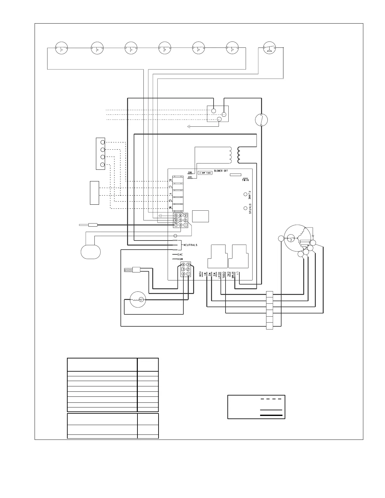
Figure 22. G6RA Integrated Control Board System Diagram
JUNCTION
BOX
IGNITOR
INDUCER
GAS
VALVE
VENT
SAFETY SWITCH
SUPLY AIR
LIMIT
SWITCH
TRANSFORMER
FLAME SENSOR
C
(optional)
GREEN
BLACK
WHITE
BLUE
BLUE
24 V
120 V
ORANGE
BLUE
BLUE
YELLOW
BROWN
RED
BLACK
WHITE
ORANGE
BLUE
BLACK
ORANGE
BLACK
RED
AIR CONDITIONER
CONDENSING UNIT
BLACK
BLACK
BLOWER DOOR
SWITCH
R
WHITE
BLACK
WHITE W/ BLK STRIPES
BLK W/ WHITE STRIPES
WHITE (NEUTRAL)
BLACK 120V
GROUND
ROOM THERMOSTAT
3 OR 4 SPEED MOTOR
H
MH
ML
L
C
WHITE
RED
ORANGE
BLUE
BLACK
MOTOR
PLUG
1
2
3
4
5
6
BLACK
BLUE
BLUE
FLAME
ROLL-OUT
SWITCH
FLAME
ROLL-OUT
SWITCH
(optional)
FLAME
ROLL-OUT
SWITCH
VENT
PRESSURE SWITCH
(G6RD Only)
PRESSURE
SWITCH
BLOWER
DECK
SWITCH
(optional)
BLUE
R
Y
G
W
C
Y
180
120
90
60
WD#703768
For G6RA Residential Furnaces
Power On
Limit Circuit Open
Pressure Switch Stuck Open
Pressure Switch Stuck Closed
Ignition Failure (Check Ground)
115 VAC & Neutral Reversed or no Ground
False Flame or Gas Valve Relay Shorted
ON
1 FLASH
2 FLASHES
3 FLASHES
4 FLASHES
5 FLASHES
Continuous
STATUS
RED
LIGHT
FAULT CONDITION
Legend
Field Wiring
Factory Wiring:
Low Voltage
High Voltage
If any of the original wire as supplied
with the furnace must be replaced, it
must be replaced with wiring material
having a temperature rating of at least 105 C.
Power Off
Low Flame Sensor Signal
Flame Present
Continuous
Flash
OFF
ON
FLAME
YELLOW
LIGHT
FAULT CONDITION
 Loading...