34 G6RA, G6RK Service Manual
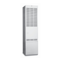
Gas Valve (See Figure 45.)
The G6 series furnaces use Honeywell valve VR8205A2008.
Gas valves are 24 vac operated. There are ports on the
valves to read incoming supply pressure and manifold or
burner pressure. Supply pressure for natural gas should be 5-
7" W.C. LP gas should be 11-13" W.C. Manifold pressure for
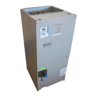
natural gas should be 3.2" W.C. (see Figure 46) and LP gas
should be 10" W.C. (see Figure 45).
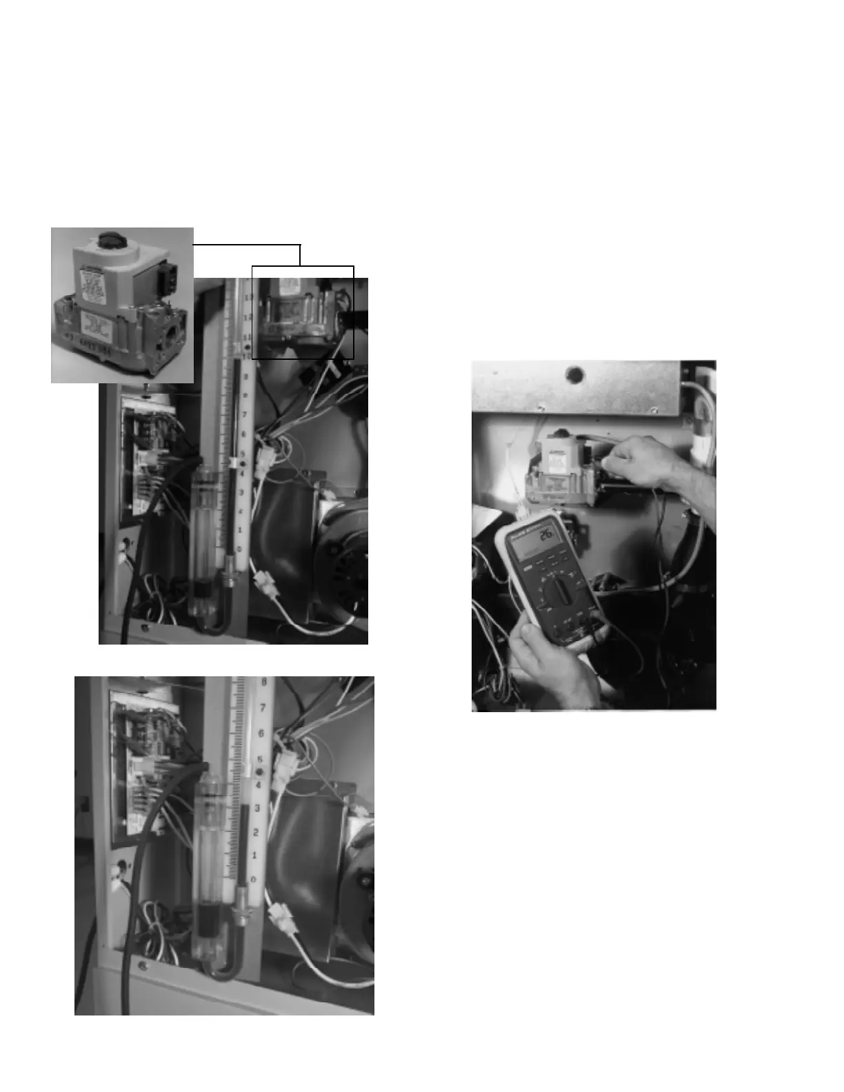
Check-out Procedure
1. By using a volt meter on a 24 volt scale, position the
probes at the gas valves.
2. Establish a call for heat.
3. After furnace has operated for approximately 60 seconds,
the gas valve receives 24 vac from the control board.
(See Figure 47.)
4. If gas valve does not open, verify gas inlet pressure is
available and not above 14" W.C., then replace valve.
Note: High inlet gas pressure will lock down valve.
5. Voltage may also be checked at the control board.
6. If voltage is not available at the control, replace control.
Gas valves have a resistance of 1.9 to 2 mega ohms. This
coil may be open or shorted.
Figure 45.
Figure 46.
Adjusting Manifold Pressure
1. With gas valve in the off position, remove the outlet
pressure cap screw using a 3/16" Allen wrench.
2. Connect a U-tube manometer or gauge to read pressure.
3. Turn on gas valve and establish call for heat.
4. Read pressure on U-tube manometer or gauge.
5. Adjust pressure as necessary:
a. 3.2" W.C. for natural gas
b. 10" W.C. for LP gas
6. If an adjustment is needed, remove pressure regulator
cap. Turn the adjustment screw clockwise to increase
pressure and counterclockwise to decrease pressure.
7. Replace regulator cap and shut off valve to remove U-
tube or gauge. Reinstall pressure cap screw.
Figure 47.
 Loading...