16 G6RA, G6RK Service Manual
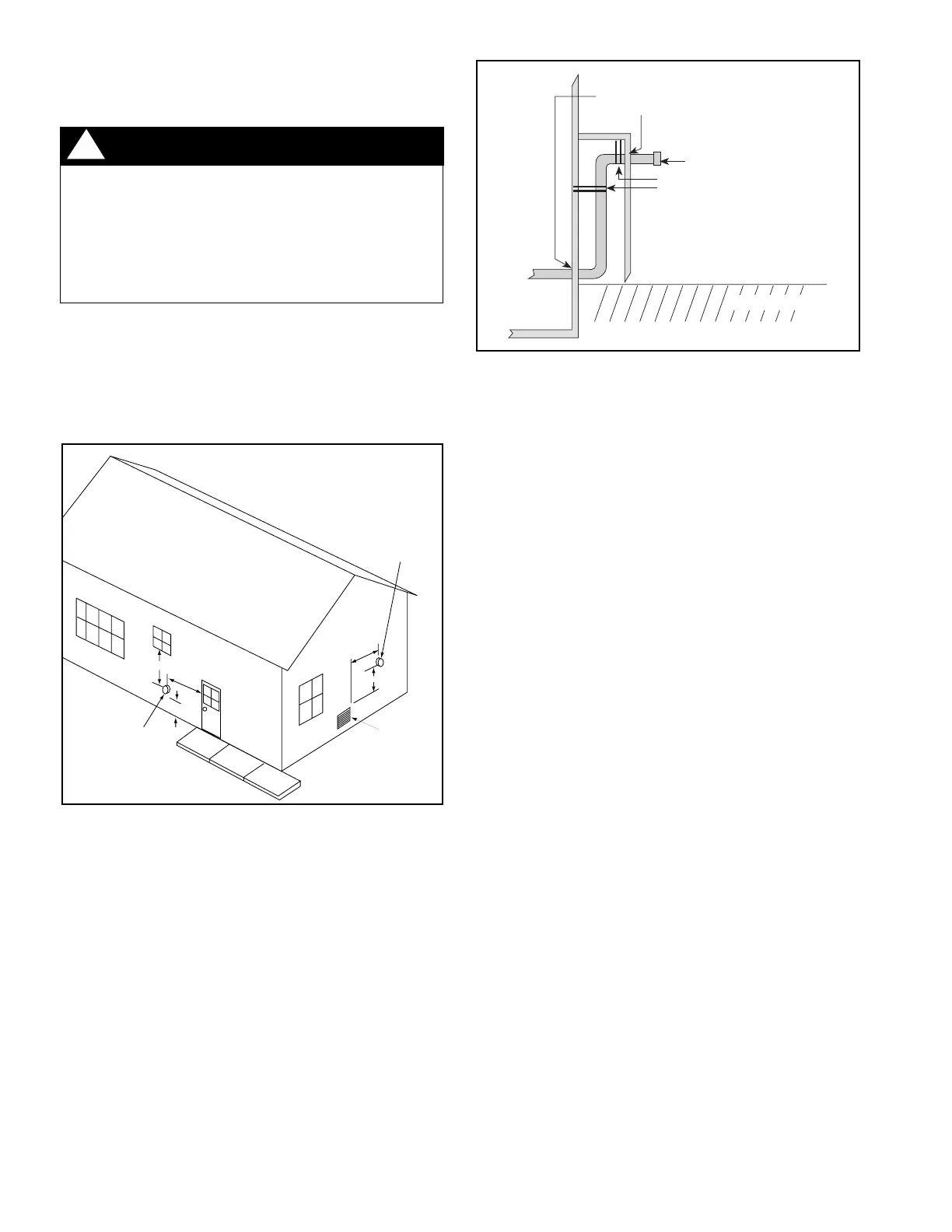
4 ft. min
4 ft. min
12 in. min
Mechanical
draft vent
terminal
Mechanical
draft vent
terminal
Forced
Air Inlet
Grade
Less
than 10 ft.
3 ft. min.
Flexible Vent Systems
WARNING:
The entire vent system must be sealed with
a high temperature sealant which will
withstand temperatures of 450°F.
Recommended sealants: Dow Corning
Sealant 736 RTV; GE 106 RTV; High Tech
Ind., High TEMP RED.
!
Location of Outdoor Terminations
Horizontal Installation
The vent termination tee must be installed with the
following minimum clearances. (See Figure 15.)
Figure 16. Alternate Horizontal Vent Installation
1. The termination tee must be 12 inches above snow
level or grade level which ever is higher. See Figure 16
for alternate method to achieve 12" above snow level.
2. The minimum distance from any door, (openable)
window, or gravity air inlet is 4 ft. below, 4 ft. horizontally,
or 1 ft. above.
3. The vent termination shall be a minimum of 3 ft. above
any forced air inlet within 10 ft. (See Figure 15.)
4. Recommended minimum distance from an inside corner
formed by two exterior walls is 6 ft., but is not required.
5. The minimum distance from gas or electric meter(s) is
4 ft.
6. Avoid areas where condensate drainage may cause
problems such as above planters, patios, or adjacent
to windows where the steam from the flue gases
may cause fogging. Do not terminate above any
public walkway.
7. Select the point of wall penetration where the minimum
1/4 inch per foot of upward slope can be maintained.
8. When penetrating a noncombustible wall, the hole
through the wall must be large enough to maintain the
pitch, pipe clearance for passage, and provide for
proper sealing. Penetrating a combustible wall
requires the use of a wall thimble. (See Figure 22.) A
6-1/2 inch square framed opening is required to insert
the thimble halves. The thimble is adjustable to
varying wall thickness and is held in place by
applying sealant to the male sleeve before assembly.
Also run a bead of sealant around the outer wall
thimble.
9. The vent pipe must extend 1-1/4 inches through the
outer thimble half for a combustible wall. Be sure to
check this carefully before cutting the vent pipe.
10. Attach a 3 inch coupling to the end of the pipe that
extends through the wall or thimble. This prevents
the vent pipe from being pushed inward.
11. Cut an 8 inch minimum piece of vent pipe and
connect the coupling to the termination tee. The
inside of the tee must be a minimum of 12 inches
from the outside of the wall. (See Figure 17.)
Figure 15. Vent Termination Clearances
Use Wall Thimble at
Vent Points
Support
Ground Level
Termination Tee
 Loading...