14 G6RA, G6RK Service Manual
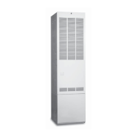
Figure 10. Limit Circuit Wiring
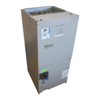
Bleed Tube
Bleed Tube
Orifice
Collector
Pan
Pressure
Switch
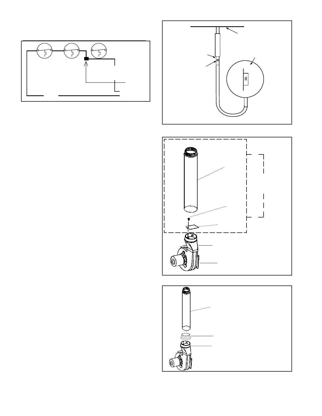
Transition
Inducer
Remove
and
Discard
Figure 13. G6RK Reducer Installation
Figure 12. G6RK Horizontal Vent Modification
Figure 11. G6RK Bleed Tube Installation
Combustion
Tube
Screw
Restrictor
Plate
Transition
4" to 3" Reducer
Special 3"
AL29-4C
Stainless Steel
Vent Pipe
Wire Nut
Switch
Limit
Switch
Flame
Roll-Out
Switch
Vent
Limit
Blue
Blue
1. By-pass the vent switch, located on blower
compartment door, by removing both wires from the
switch. Remove wire terminals, strip wires and tie
together in a wire nut. (See Figure 11.)
2. Remove the rubber tubing from the pressure switch
sensor tube and the collector pan sensor tube. Cut the
tubing approximately 3" from one end and insert the
bleed tube into the tubing. Do not cover the hole in
the bleed tube. Place the tubing assembly back on
the pressure switch sensor tube and collector pan
sensor tube. (See Figure 11.)
3. To gain access to the restrictor plate, remove and
discard the combustion tube from the transition
assembly. Insure the seal between inducer and
transition assembly is not broken. (See Figure 12.)
4. Remove and discard the restrictor plate and screw
from the transition assembly. (See Figure 12.)
5. Install and seal a 4" to 3" reducer to the transition. (See
Figure 13.) Attach the new high temperature vent pipe
to the reducer.
The components of the horizontal vent system must not be
penetrated, with screws, rivets, or other devices, either when
joining pipes and fittings or using support straps. All joints
must be sealed with high temperature silicone before locking
 Loading...