G6RA, G6RK Service Manual 35
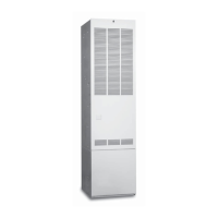
Flame Sensor (See Figure 48.)
The flame sensor is located in front of the first burner. After
the burners are ignited, flame is proven through the flame
sensor by flame rectification. The sensor is an alloy consisting
of aluminum, chromium, and iron. This alloy is commonly
known as Kanthal D.
Check-out Procedure:
1. Use a micro amp meter or the micro amp setting on a
digital volt/ohmmeter to measure the flame current
signal. (uA scale.)
2. Disconnect flame sensor at the push-on connector below
the burner assembly.
3. Put meter probes in series with flame sensor connectors.
4. Establish a call for heat.
5. After flame is established, note micro amp reading.
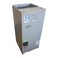
6. A strong signal is 3 to 4 uA. (See Figure 49.) The board
will close the gas valve if the micro amp reading is less
than 0.5 uA.
Studies have shown that silicone oxides may accumulate on
the sensor. It is important that the furnace operates in an
environment which is conducive to proper furnace operation.
These oxides can be removed by brushing with steel wool.
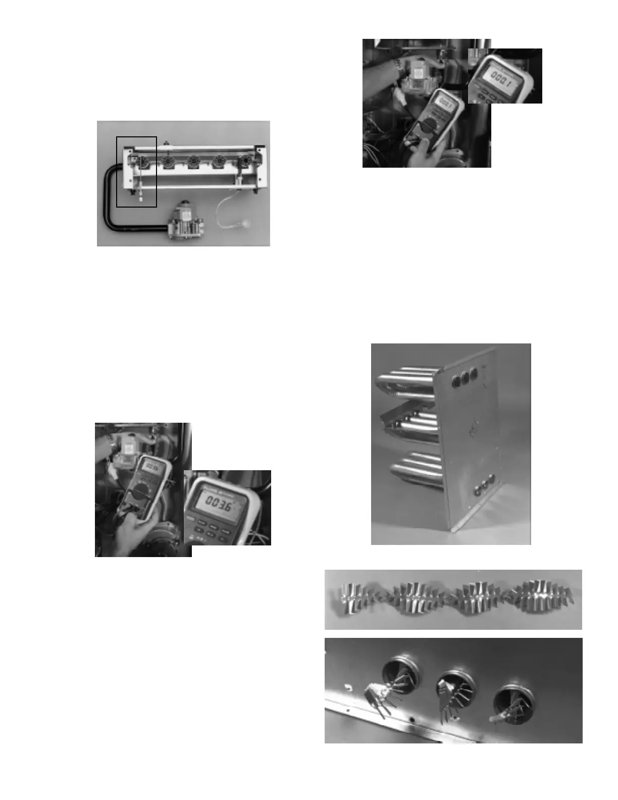
Heat Exchanger and Its Components
The G6 uses a tubular type of heat exchanger made from
aluminized steel. (See Figure 51.) Inside the heat exchanger
are the tubulators, located in the last passage of each tube,
behind the collector box. They help in the efficiency of the
combustion process. (Figure 52.)
Figure 48.
7. To aid in troubleshooting, the ignition control has a yellow
flame signal light. If the light is on, flame signal is at 1 or
higher micro amps. If the light is blinking, signal is below
1 uA and is weak.
Reasons for Poor Micro Amp Readings (See Figure 50.)
1. Dirty flame sensor.
2. Poor positioning of flame sensor.
3. Poor ground on furnace.
4. Low gas pressure.
5. High gas pressure.
Figure 49.
Figure 50.
Figure 51.
Figure 52.
 Loading...