20 G6RA, G6RK Service Manual
Furnace Furnace Cabinet Nominal Maximum Minimum Maximum Minimum Maximum
Model Input Width Electrical Operating Operating Furnace Wire Fuse or Circuit
Number (Btu/hr) (in.) Supply Voltage Voltage Amperes Gauge Breaker Amps**
G6R(A,K)
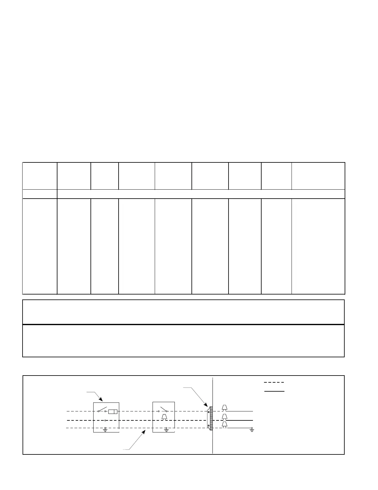
045(*)-08 45,000 14.25 115-60-1 127 103 4.9 14 15
060(*)-12 60,000 14.25 115-60-1 127 103 8.9 14 15
072(*)-12 72,000 14.25 115-60-1 127 103 8.9 14 15
072(*)-16 72,000 19.75 115-60-1 127 103 11.3 14 15
096(*)-12 96,000 19.75 115-60-1 127 103 8.9 14 15
096(*)-16 96,000 19.75 115-60-1 127 103 11.3 14 15
096(*)-20 96,000 22.50 115-60-1 127 103 15.3 12 20
120(*)-16 120,000 19.75 115-60-1 127 103 11.3 14 15
120(*)-20 120,000 22.50 115-60-1 127 103 15.3 12 20
144(*)-20 144,000 22.50 115-60-1 127 103 15.3 12 20
Field Supplied
Disconnect Within
Sight of Furnace
Field Supplied
Panel Connector
Field Supplied
Fused Service
Panel
Black (Hot)
White (Neutral)
Green or Bare (Ground)
Black
White
Black
White
Black
White
Field Line Voltage
Wiring
Factory Line
Voltage Wiring
Ground
Ground
Ground
Line Voltage Wiring (See Figure 15)
The line voltage (115 volt) to the furnace must be supplied
from a dedicated circuit containing the correct fuse or circuit
breaker for the furnace. See Table 5. An electrical switch
should be readily accessible from and within sight of the
furnace. All line voltage connections must be made within the
furnace, or in a junction box.
The furnace cabinet must have an uninterrupted, unbroken
ground to minimize injury should an electrical fault condition
occur. The controls used in this furnace also require an earth
ground to cooperate properly. Acceptable methods for
grounding are electrical wire or conduit approved for electrical
ground service. Do not use gas piping as an electrical ground.
NOTE: Proper line voltage polarity must be maintained
in order for the control system to operate correctly. Verify
that the incoming neutral line is connected to the white
wire and the incoming "hot" line is connected to the
black wire in the furnace junction box. The G6 series
furnaces will not operate unless polarity and ground are
properly connected. (See Figure 24.)
Never use gas lines as ground.
To determine polarity, the incoming power supply should be
checked. The "Hot" lead will read 115V to ground. The
"neutral" should read 0V to ground.
Supply Voltage
Supply voltage to the furnace should be nominal 115 volts. It
must be between 103 volts and 127 volts. Supply voltage to the
furnace should be checked with furnace in operation. Voltage
readings outside the specified range can be expected to cause
operating problems. Their cause MUST be investigated and
corrected.
Table 5. Electrical Data
Figure 20. Line Voltage Field Wiring
Thermostat Wire Gauge
24
22
20
18
2-wire
(heating)
55 ft.
90 ft.
140 ft.
225 ft.
Recommended Thermostat Wire Length
4 or 5-wire
(cooling)
25 ft.
45 ft.
70 ft.
110 ft.
 Loading...