G6RA, G6RK Service Manual 27
A. 90 second delay blower "off" time in cooling mode.
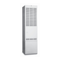
B. Low Voltage Fuse - an over-current, short circuit safety
device designed to protect the control board in the event
of a low voltage short or over-current. (See Figure 30.)
C. Field Adjustable Fan Settings (Heating Mode)
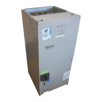
D. Humidifier & Electronic Cleaner Tap - Both taps are rated
at 1 amp and have an output voltage of 120 VAC. All
humidifiers and electronic air cleaners should be installed
per the installation instructions the manufacturer supplied
with their equipment. (See Figure 32.)
Note: A 24 volt humidifier solenoid coil must not be wired
across the "W" and "C" terminal. This will interfere with
the operation of the control board and may influence the
heat anticipator in the thermostat.
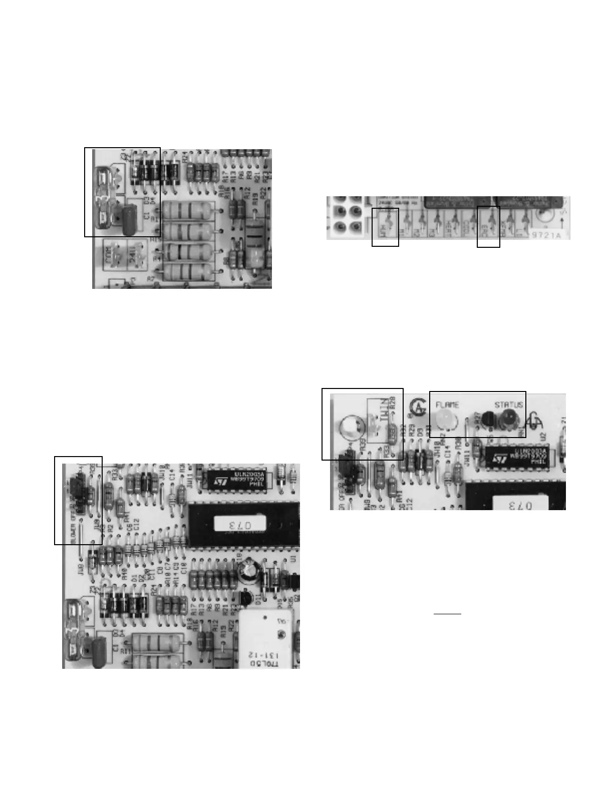
The off times are field adjustable and may be set from
180, 120, 90, 60 seconds; 120 being set from the factory.
To change the off-time, remove jumper pin and replace
it on the desired time. Time-on is fixed at 30 seconds.
(See Figure 31.)
E. Twinning Terminal - The function of twinning is to insure
simultaneous blower operation on two furnaces. The G6
series is twinning ready. The 3/16" quick connect terminal
on the board must be connected to the other furnace
control. The thermostat wiring is provided in the diagram.
See Figure 33 for location and Figure 18 on page 18 for
Twinning Diagram.
Figure 30.
Figure 32.
Figure 33.
F. Diagnostic Lights - the diagnostic light feature is to aid
the service technician in identifying the nature of the
problem. See Figure 33.
1. Red Status Light. An explanation of the flash code
may be seen on the inside of the door. Note: The light
must be observed before the bottom door is removed
since the board does not store the fault condition in
its memory. See Table 6.
2. Yellow Flame Light. This will come on solid with a
flame signal of 1uA or more. The flame light will blink
at the point of a weak signal and go out at any reading
of .5 uA or less. See Flame Sensor section on page
34.
Figure 31.
 Loading...