26 Miscellaneous PCA Replacement Procedure
297-6201-501 97Q3 Standard 02.01 July 1997
6 Enter the following commands to write the value 00 in the
DRAM memory address 2204 for the off-line DSI/TEC PCAs:
>MONS (cr)
>TEC1CA2204W00 (cr)
>(ESC)
>TEC2CA2204W00 (cr)
7 Remove power from the standby BMC chassis by operation of
the +8 V dc red rocker switch on the power supply.
(A or B, the one with the suspected fault.)
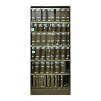
8 Remove the suspected faulty PCA.
9 The replacement PCA option settings must be set to match the
settings for that PCA listed in the PCA Switch and Strap Set-
tings section before installation.
CAUTION
Failure to set-up options correctly may cause an AMA loss.
10 Insert the spare PCA in the vacated card slot, making sure it is
fully seated.
11 Put faulty PCA in the empty electrostatic bag.
12 Apply power to the BMC chassis by resetting the rocker switch
in step 7 above.
Wait for start-up activity to end and the message, Software
Loaded or S/W Loaded to print.
13 To clear any alarms on the standby processor. At the mainte-
nance terminal, enter:
>MONS (cr)
>RSERR 00 (cr)
>(CNTL) Z (cr)
Alarms will clear on the standby processor if there are no
faults.
14 Place the active processor unit in PRIME mode. At the Switch
and Status Panel of the BMC:
a. Press the A/B Select Switch to match the active processor.
b. Press the O/P Mode Select Switch to P.
c. Turn the Mode Switch to the right and release.
15 To clear all alarms on the active processor. At the maintenance
terminal, enter:
>RSERR (cr)
Alarms will clear if there are no faults.
Procedure 1
Miscellaneous PCA replacement
Step Description