41
BMC II BISYNC Quick Reference Guide
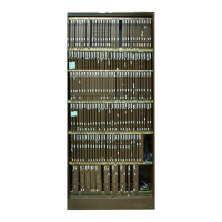
Power and Alarm Communications PCA
Replacement Procedure (NT6M84xx)
Procedure 7
Power and Alarm Communications PCA (NT6M84xx)
replacement
Step Description
CAUTION
Since all BMC PCAs are static sensitive, be careful when
handling them. Wear a wrist grounding strap when working
with the BMC.
WARNING
Since the BMC is powered up during this procedure, observe
all safety procedures for operations on live equipment.
1 Make sure no polling is occurring. Wait for a low traffic period,
if possible.
2 Remove the slotted screws that fasten the outer edges of the rear
panel assembly to the cabinet.
3 Remove the front panel of the A chassis. Put the two panels in
a safe place to prevent bending and scratching.
4 Remove the power from the PCA first by disconnecting (P11)
located in the upper right quadrant. Remove the other cables.
Note: Verify the cable markings (identification) or attach labels to the
cables when removing them to facilitate replacement in the correct posi-
tions.
Alarms may also activate and the BMC status panel lights will
all be off. This is normal. Silence the alarm at the switching
system and go to step 5.
5 Remove the screws that fasten the P/A Comm PCA. Gently
remove the PCA from its mounting position.
6 The replacement PCA option settings must be set to match the
settings for that PCA listed in the PCA Switch and Strap Set-
tings section before installation.
Note: Improper performance can be caused by incorrect settings, and
produce fault-like symptoms in the BMC.
7 Mount the replacement PCA in the vacated position.
Note: When replacing the screws, align carefully before tightening to
avoid stripping. Tighten the screws, alternating until all are equally
tight. Do not “cinch down” any one screw until all are properly aligned;
no binding or force needed to turn.