96 AFP-200 Instruction PN 15511:F2 10/11/99
Appendix E Combination
Fire/Burglary Applications
The control panel can be used as a combination Fire/Burglary and Burglary system when operated according to
the requirements in this appendix.
Note: The control panel uses the same trouble input connector for the door tamper switch (STS-200) and the
AVPS-24 power supply expander. Therefore, the control panel cannot be used in Fire/Burglary applications if
an AVPS-24 is installed and programmed.
General Operation
For security applications, one or more Monitor Modules must be programmed with the “BURGLAR ALA” type
code and must be wired as described in this appendix. Activation of such a Monitor Module will light the
yellow Security LED and the control panel LCD display will indicate a burglar alarm condition. The piezo will
sound until acknowledged. Additional sounders or output devices may be programmed to activate with the
burglar alarm initiating device. The Burglar Alarm type circuit is designed to indicate an alarm on an open or
short circuit, or a resistance change of 50% (plus or minus) from the end-of-line resistor value. A tamper switch
installed in the cabinet will also indicate a security alarm whenever the door is opened.
The BURGLAR ALA or DOOR TAMPER indication may be acknowledged, silenced, or reset from the control
panel.
When the system is reset, a 30-second exit timer starts. During this time, the tamper switch and all Burglar
Alarm type alarms are ignored. There is no entrance delay timer.
For instructions on bypassing security zones for Burglar alarm type devices, refer to the Disable/Enable section
in Chapter 3, Programming.
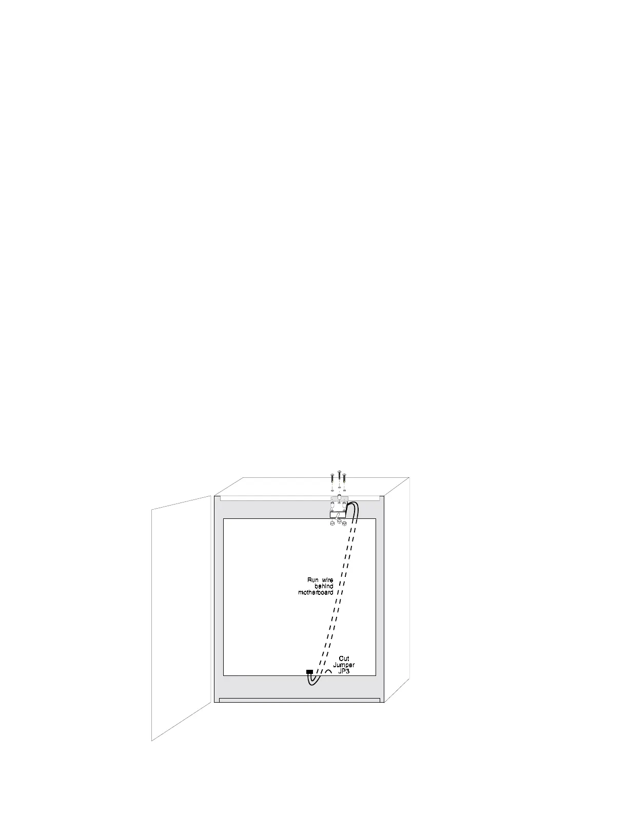
Tamper Switch
The cabinet must be wired with the STS-200 security tamper switch kit as shown in Figure E-1.
J11
Figure E-1 Typical Wiring of an STS-200 Tamper Switch