AFP-2800 - Fire Indicator Panel – Panel Operation Page 31
©
N
OTIFIER
I
NERTIA
P
TY
L
TD
,
2001
WWW
.
INERTIA
.
COM
.
AU
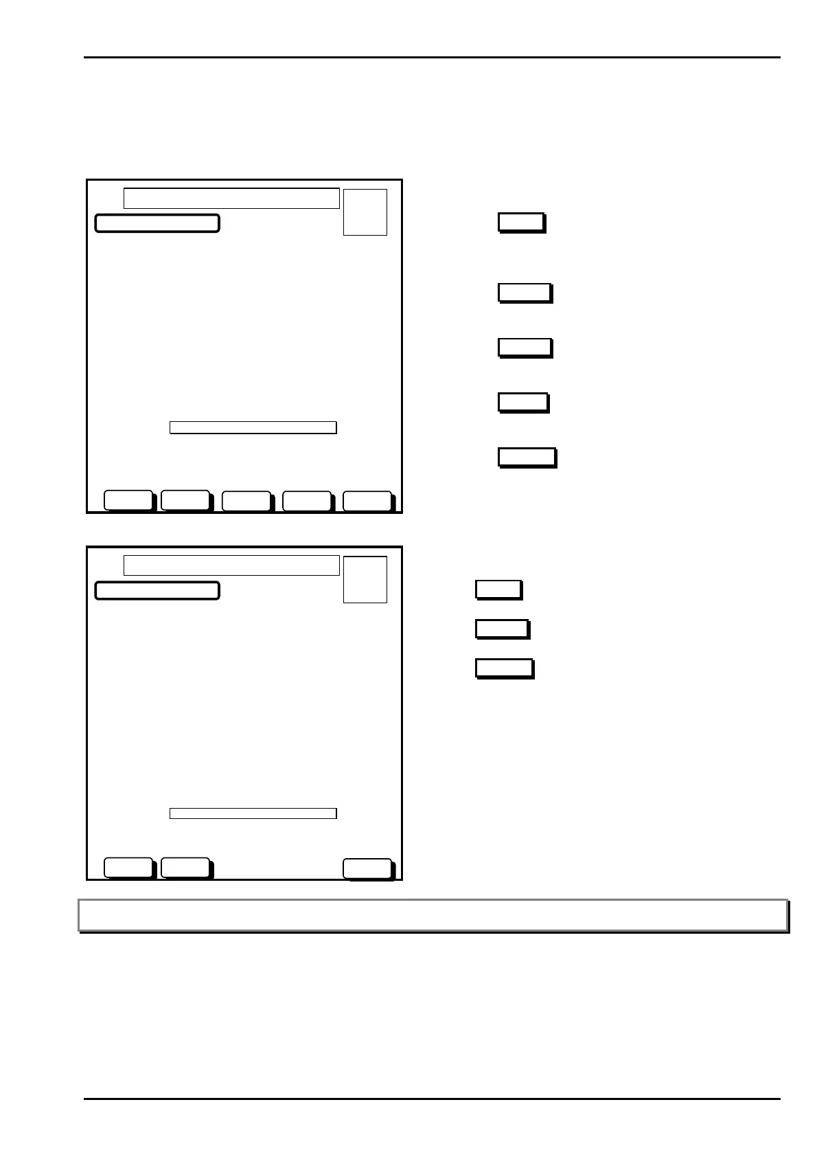
Service Menu - List – FlashScan – Modules – Status – Test
This screen will perform functional tests on selected FlashScan points. As modules can be both inputs and
outputs, there are two different modes of operation.
If module is an Input Module
L1M1 > BREAK GLASS ON PANEL
Poll Mode > Flashscan Mode
Programmed As > FMM-101-MMX-101 MINI MON
Actual Device > FMM-101 MINI MON
Device State > NORMAL
Device Status > NORMAL
LED Status > Polling
USE BUTTONS TO SELECT TEST .
FLASHSCAN MENU – TESTING
A = 0
F = 0
I = 0
N = 0
01 OCT 1999 14:44:37
FS-OFFFS-ON
FS-ALM STATUSFS-FLT
Actions:
Press the FS-ON
button to turn module LED’s ON
Green (Red if CLIP). (This test is useful for locating
detector/detectors at same address)
Press the FS-OFF
button to return module LED’s to
the Automatic Polling Mode
Press the FS-ALM
button to perform an ALARM
TEST on the module.
Press the FS-FLT
button to perform an FAULT TEST
on the module.
Press the STATUS
button to return to the read status
screen.
If the module is an Output Module.
L1M10 > EWIS OUPUT #1
Poll Mode > Flashscan Mode
Programmed As > FRM-1/CMX-2 Relay O/P
Actual Device > FMM-1 Relay
Device State > NORMAL
Device Status > NORMAL
LED Status > Polling Green
USE BUTTONS TO SELECT TEST .
FLASHSCAN MENU – TESTING
A = 0
F = 0
I = 0
N = 0
01 OCT 1999 14:44:37
FS-OFFFS-ON
STATUS
Actions:
Press FS-ON
to activate the output module.
Press FS-OFF
to de-activate the output module.
Press STATUS
to return to the read status screen.
Note: Script processing is paused during an output module test. Scripts will automatically resume processing once a test is
complete.
www.PDF-Zoo.com
 Loading...


