5 AFP-3030 Operations Manual — P/N DOC-01-039:A 26/11/2015
General Information Operating Features
NEXT/PREVIOUS - Use these keys to scroll through the list of possibilities in a data field on the
display screen.
PRINT - Press this key to print what is displayed on the display screen.
BATT - Press this key to display power supply battery levels on the display screen.
LAMP - Press this key to test the LED indicators on the keypad and the piezo. Pressing the key
longer than 5 seconds will display firmware version numbers on the display screen.
LED Indicators
There are nineteen labelled LEDs on the keypad. They light to annunciate certain conditions, as
described in Table 1.2 below.
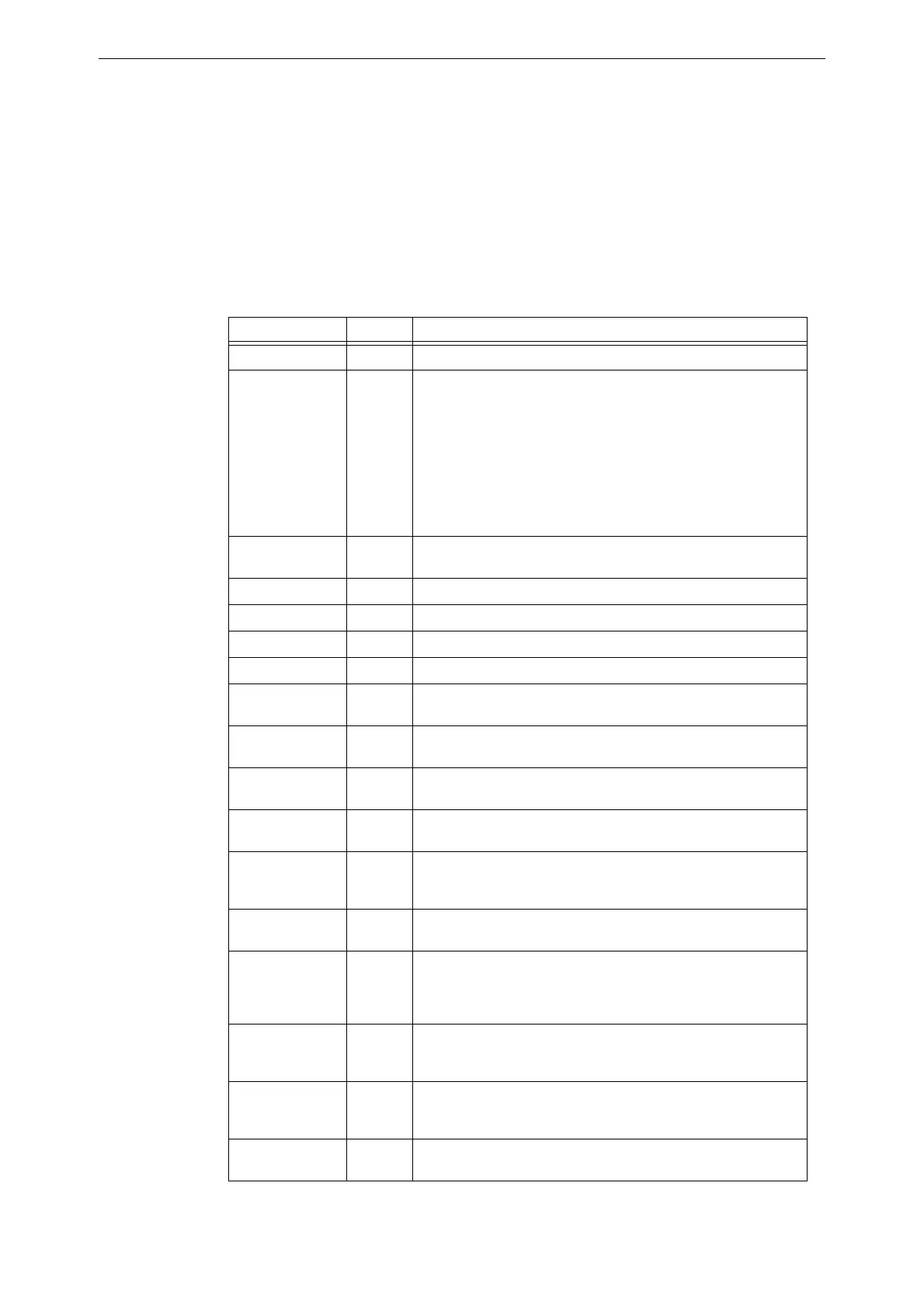
LED INDICATOR COLOR FUNCTION
Fire Red Illuminates when there are fire events in the system.
System Normal Green Illuminates when system power is on and the system is functioning as
expected.
Not illuminated when:
-Main Power Supply is too low
-Backup battery supply is too low
-Panel has a CRC Fault on firmware or database
-Loses communication with another node (when in Network Display
Mode)
-Loses communication with the LCM
-Loses communication with the ACM-PSI
Alarm Routing
Equipment Act.
Red Illuminates when the A.R.E. Alarm Routing Output is active.
Several Alarms Red Illuminates when more than one fire event is present on the panel.
System Fault Yellow Illuminates when at least one system fault exists on the fire panel.
Fault Yellow Illuminates when at least one fault event exists on the fire panel.
Disable Yellow Illuminates when at least one device on the fire panel is disabled.
Supervisory Yellow Illuminates when at least one supervisory event is present on the fire
panel.
Alarm Routing
Fault
Yellow Illuminates when there are any device or system trouble event is
present on the A.R.E. Alarm Routing Equipment
Alarm Routing
Disabled
Yellow Illuminates when at least one device or zone on the A.R.E. Alarm
Routing Equipment is disabled.
Alarm Devices
Silenced
Yellow Illuminates when devices programmed as Alarm Devices are silenced.
Alarm Devices
Fault
Yellow Illuminates when any devices designated as Alarm Devices are in
fault, including communication loss with the Alarm Devices or the LCM
that has programming containing Alarm Devices.
Alarm Devices Test Yellow Illuminates when Alarm Devices are activated due to pressing the
Alarm Devices Test button.
Alarm Devices
Disable
Yellow Illuminates when Alarm Devices are disabled due to pressing the
Alarm Devices Disable button.
Note: This LED will not illuminate if the Alarm Devices are disabled via
the menus or the network.
Door Holder
Disable
Yellow Illuminates when the Door Holder devices are disabled via the Door
Holder Disable button. This LED will remain lit until the Door Holder
Disable button is pressed a second time to re-enable the devices.
Auxiliary Disable Yellow Illuminates when the Auxiliary Devices are disabled via the Auxiliary
Device Disable button. This LED will remain lit until the Auxiliary
Disable Button is pressed a second time to re-enable the devices.
Delays On/Off Yellow Illuminates when the Outputs are delayed via the Delays - On/Off
button.
Table 1.2 LED Indicators (1 of 2)