MT 4100 User Guide 10
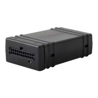
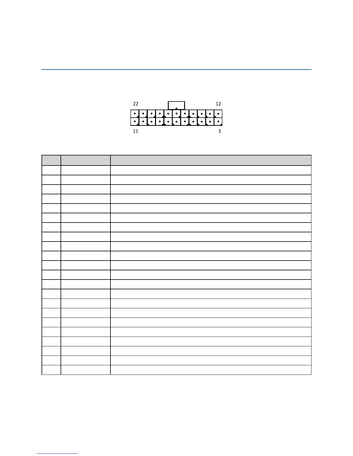
22-Pin I/O Connector
The MT4100 has a 22-pin I/O connector. The following image shows the pin layout.
The 22-Pin I/O Connector provides the following functionality:
Pin # User Name Description
1 Digital Input #5 Digital Input #5 (GPI12)
2 Digital Input #4 Digital Input #4 (GPI11)
3 1-Wire 1-Wire® Interface / Note: Maximum voltage on this pin is 3.3 VDC
4 ADC In #2 Analog-to-Digital Input, 0 – 32 VDC
5 ADC In #1 Analog-to-Digital Input, 0 – 16 VDC
6 Ground System Ground
7 Ground System Ground; Connector has longer pin for MFBL
8 Digital Input #2 Digital Input #2 (GPI9)
9 Digital Input #1 Digital Input #1 (GPI1)
10 RS-232 CTS1 RS-232 CTS1 Out / Note: Output only. Input voltages should not be applied.
11 Ignition Sense Vehicle Ignition Sense
12 RS-232 TX2 RS-232 TX2 In / Note: -25 VDC to 25 VDC
13 RS-232 RX2 RS-232 RX Out / Note: Output only. Input voltages should not be applied.
14 Digital Output 1 Output, High-Current Sink, Low-Current Source, Latched (GPO2)
15 Digital Output 2 Output, High-Current Sink, Low-Current Source, Latched (GPO5)
16 Digital Output 3 Output, High-Current Sink, Latched (GPO3)
17 Power In Vehicle Power from 12 or 24 V Vehicles
18 Power In Vehicle Power from 12 or 24 V Vehicles
19 Digital Input #3 Digital Input #3 (GPI10)
20 RS-232 RTS1 RS-232 RTS1 In / Note: -25 VDC to 25 VDC
21 RS-232 TX1 RS-232 TX1 In / Note: -25 VDC to 25 VDC
22 RS-232 RX1 RS-232 RX1 Out / Note: Output only. Input voltages should not be applied.