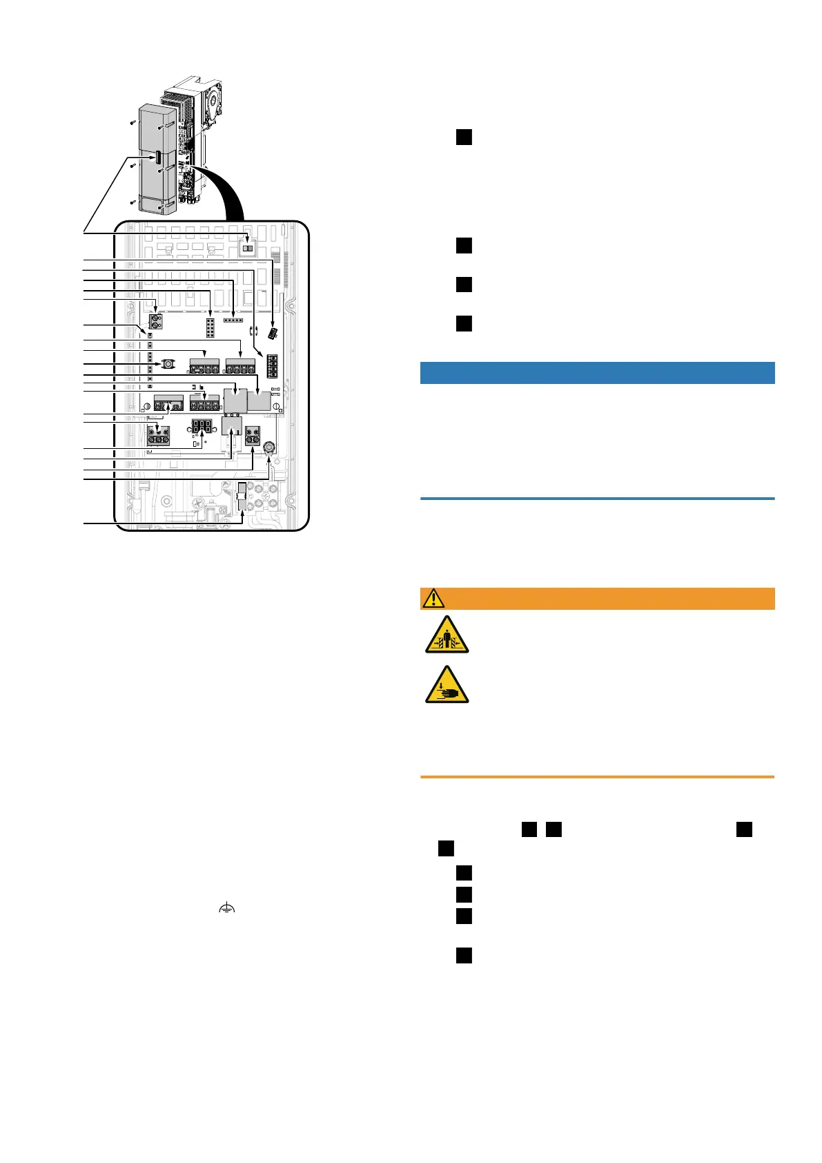
4.4.1Connection diagram overview
LED
J6
J9
J11
J10
J5
J4
J3
PROG
J2
J1
J12
J13
J15
J14
X2
F1
X1
J7
J8
LED LED red/blue for operation/programming
PROG PROG button, activates programming mode
J1 Connection of external control device/ control device IPD-E/IPD-E KS
J2 Input for photoelectric sensor
J3 Input for door connection box
J4 Input for roll-up protection mechanism
J5 Slot for radio module (ISM 433/868)
J6 Slot for service/option module
J7 TM-BUS connection (control device IPD-S/ IPD-S KS, EDL100)
J8 Battery serial interface
J9 BTD-K slot (Bluetooth dongle)
J10 Slot for option module (prioritised input, interlock, output status relay2)
J11 Programming interface
J12 Output status relay1 (potential-free contact)
J13 Connection of supply voltage via battery
J14 Output. 24 V DC/700 mA
J15 Motor connection
X1 Antenna
X2 Connection of functional earth
F1 Fuse 5 x 20 3.15AT
4.4.2Electrical connection of further components
1. Using additional cable glands
If further cable feed-throughs are required for the installation, you can open
them as follows:
Fig.
To open a cable gland for an M16 cable gland, place a suitable slotted
screwdriver in the circumferential joint (predetermined breaking point) at various
points. Break out the material by gently hammering on the screwdriver. Loosen
the cable gland attachment and place it on the cable to be fed through. Push the
cable of the required length through the cable gland and secure the cable by
tightening the attachment on the cable gland.
Fig.
Push the supplied cable glands through the corresponding openings and
secure them with the corresponding nuts.
Fig.
If the M20 push-in fitting is to be used, carefully break out the are
marked in the illustration (e.g. by using pliers).
Fig.
Put on the push-in gland and guide the cable through it.
2. Mains connection
NOTICE
Checking the mains connection
n Ensure that on-site fusing of 10A is available.
n Check whether the mains connection on site complies with the pre-wired mains
connection of the door drive (10ACARAplug).
n Only use all-current sensitive residual current circuit breakers of typeB for on-
site fusing.
The DCC is wired in a ready-to-connect fashion using a cable and mains plug
(10ACARAplug) as shown in the illustration. In doing this, ensure that the sup-
ply disconnection is easily accessible after the installation.
3. Input J1– External control device
WARNING
Crush hazard and risk of being struck by the closing door!
Please note that when using a control device for dead man/emergency
operation, the movements of the door must be monitored. Otherwise,
people can be crushed or hit by the garage door.
n The control device must be mounted within sight of the door and at
a safe distance from moving parts.
n If the control device cannot be locked against unauthorised opera-
tion and if it is not a key switch, place the control device at a height
of1.5m and make sure it is inaccessible to the public.
Connect external control devices and pulse generators to connection ter-
minalJ1. Connect a bridge between connection terminal J1.3/4 if no STOP but-
ton is used. For fig.
/
, set menu item51 to the value1. For fig.
/
, set menu item51 to the value2.
Fig.
Connection for control device with OPEN, STOP and CLOSE.
Fig.
Connection of pulse generator OPEN, CLOSE.
Fig.
Connection of pulse generator to J1.2 with pulse sequence OPEN-STOP-
CLOSE-STOP... , or to J1.1 with pulse sequence HALF-STOP-CLOSE-STOP...
Fig.
Connection of ceiling pull switch to J1.2 with pulse sequence OPEN-
STOP-CLOSE-STOP... , or to J1.1 with pulse sequence HALF-STOP-CLOSE-STOP...
Novoferm|7