4Assembly and installation
Follow the instructions as well as the illustrations in the "Figures" chapter.
4.1Preparing for installation
n Installation work may only be carried out by qualified technicians.
n Read these installation instructions before you start installing the product.
4.1.1Scope of delivery
NOTICE
Check the supplied screws and wall plugs to make sure that they are suitable for the
structural condition on the installation site.
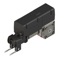
The scope of delivery is determined by the product configuration. This usually con-
sists of the DCC-80 door drive, a control device and the assembly material.
The assembly material usually contains the following components:
n 1x mounting bracket incl. 2fastening sets
n 4x hexagon bolt M8x20
n 4xspring washers A8 (DIN 127– 8.4)
n 4xwashers (DIN 9021– A8.4)
n 1x key solid shaft
n 1x key hollow shaft
4.1.2Required tools
For the assembly of the DCC, the following tools are required:
n Cross-tip screwdriver Phillips, size2
n SW13 wrench
n slotted screwdriver, 2mm
4.2Opening and closing the housing cover
The housing cover has to be opened and closed in order to carry out the assembly. To
do so, please proceed as follows.
Fig.
Loosen the 6screws on the housing cover and carefully pull the cover
straight off towards the front. The housing cover is secured against falling off with a
cord and can be left hanging from it. Adjust the housing cover so that it hangs down
from the housing.
Fig.
Carefully put the housing cover on. Ensure that you insert the light guide,
which is fixed inside the housing cover, through the guide in the non-contact safety
device of the electronic components. On the sides, there are centring areas inside
the cover which slide into the guides provided for this purpose when the cover is
placed on the housing. This provides for the cover to close properly and ensures the
sealing function. In the end, screw the housing cover to the housing using the
6screws.
4.3Mounting the door drive
NOTICE
Before installing the drive, check whether the mechanical condition of the gate is
running smoothly and whether the door is counterbalanced.
The DCC can be mounted with a mounting bracket or, alternatively, using the Univer-
sal torque support. During the assembly, observe the two applicable installation pos-
itions (fig.
installation position1 (vertical) and installation position2 (horizontal,
control unit upside down)).
Deviating installation positions are not permitted.
4.3.1Assembly with mounting bracket
Fig.
Screw the mounting bracket on the gearbox side facing the door into the
holes provided by using two M8x20 screws, spring washers and washers. Observe
the tightening torque of 15Nm.
Fig.
Grease the door shaft's areas that are in contact with the rails. Remove one
of the two screws on the key and insert the key into the groove of the door shaft. The
side without the screw must face the end of the door shaft.
Fig.
Push the drive onto the door shaft in the desired installation position and
align the gear shaft with the groove on the door shaft. Push the drive onto the door
shaft until the mounting bracket is supported on the door bracket.
Fig.
Align the key and fix the position by screwing the second screw back in.
Screw the mounting bracket to the door bracket. To do so, use the screw set sup-
plied with the mounting bracket.
4.3.2Assembly with Universal mounting bracket
A suitable and load-bearing substrate (e.g. a wall) is required for the assembly with
the Universal mounting bracket.
Fig.
Align the Universal mounting bracket with the door shaft and fasten the
door shaft to the wall. Use the supplied wall plugs and screws to fix the unit to the
wall.
Fig.
Push the door drive onto the door shaft as explained for installation with
mounting bracket (fig.
to
). Connect the door drive to the torque support with
4screws (M8x20) and washers.
4.4Electrical installation
DANGER
Hazardous voltage!
Fatal electric shock when touching live parts.
Always pull out the mains plug before working on the drive!
NOTICE
Malfunction due to defective insulation of the cables
n When connecting the cables, ensure that the cable sheath is stripped close to
the connection terminal so that the cables remains insulated from each other.
n Avoid stowing cables in the connection compartment if they are too long.
Shorten the cables if they are too long.
6|Novoferm