Chapter2 Connection
Manual of NCH02
- 14 -
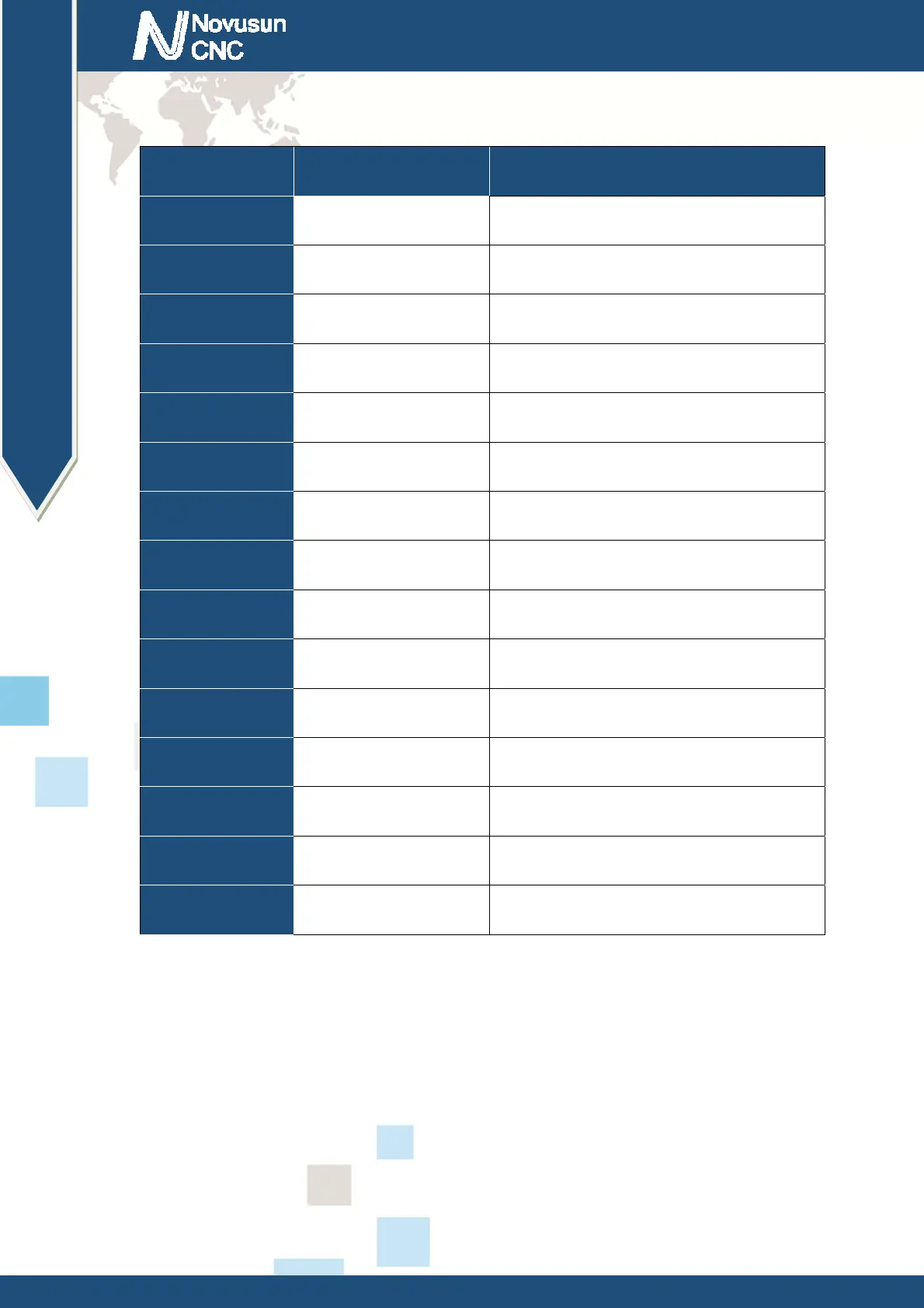
This card connect with MPG by this port. The port definition see as table 2-2
No. Mark Definition
1 T1OUT TXD of Serial port
2 VMPG Power supply + for MPG(5V)
3 WHA+ A phase positive of the encoder
4 WHB+ B phase negative of the encoder
5 XIN X axis select input
6 ZIN Z axis select input
7 X100IN 100 rate select input
8 EP Estop port
9 R1IN RXD of Serial port
10 GND Ground and common end
11 WHA- A phase positive of the encoder
12 WHB- B phase negative of the encoder
13 YIN Y axis select input
14 AIN A axis select input
15 X10IN 10 rate select input
Table 2-2. MPG port definition
2.3.6 Spindle port
As Figure 2-2 showed,No.6 port is Spindle port. The interface definition is
VSO/GND/OT1/OT2 from left to right. Where VSO is the 0-10V analog output, OT1/OT2
digital drive signal output, spindle control output interface and spindle inverter connection
diagram figure 2-11. VSO/GND/OT1/OT2 are respectively connected with the inverter
AIN1/COM/X1/X2, where AIN1 is the input speed signal, COM converter X1 and X2 are the
www.nvcnc.net
 Loading...