Chapter4
Operation and Application
Manual of NCH02
- 41 -
the XYZ axis mechanical coordinates. As shown in Figure 4-5, the plane center coordinates (X, Y,
Z) on the tool block are (30,30, -110).
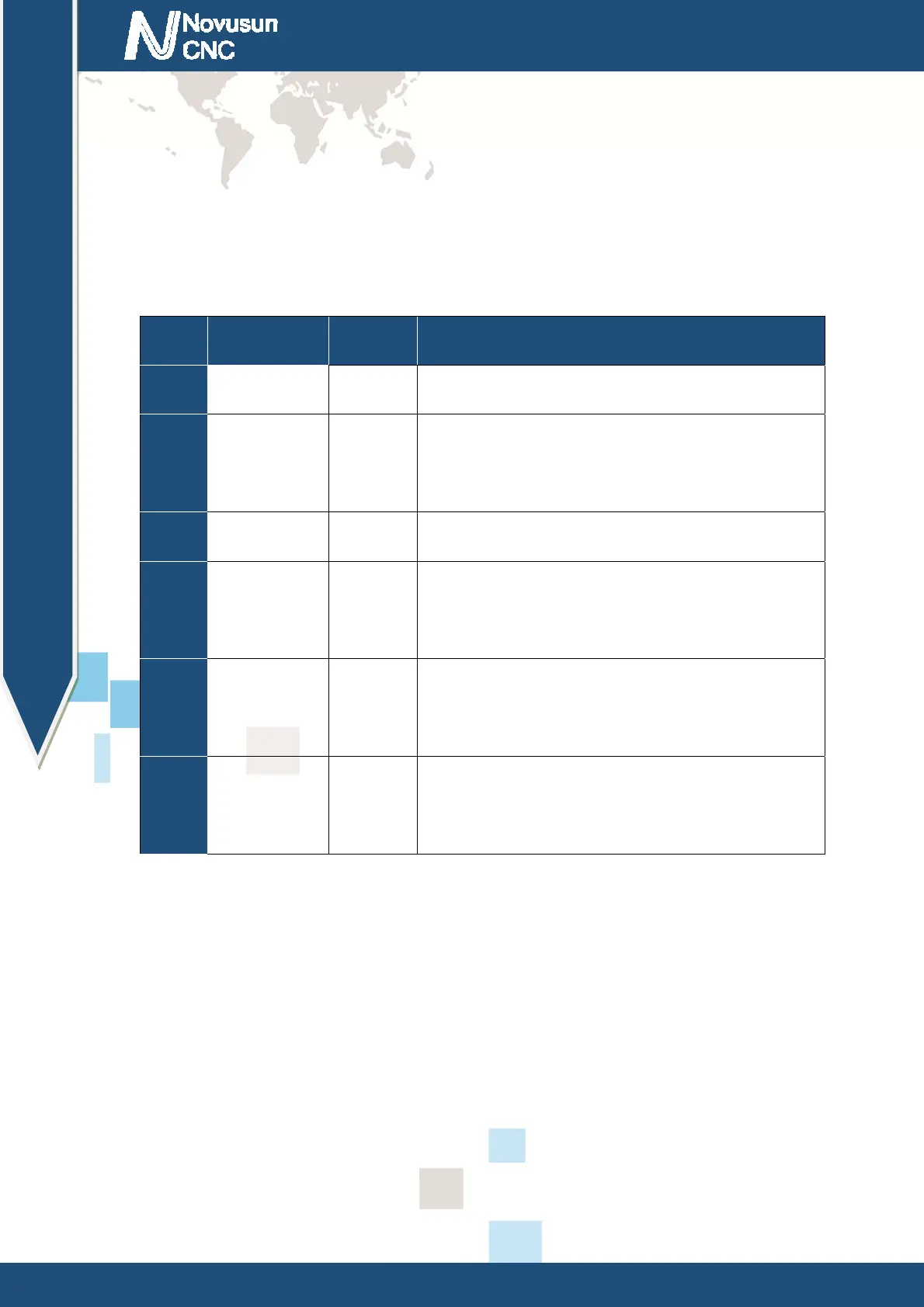
Secondly, we enter the OTHER sub page under CONFIG. As shown in Figure 4-6, we find
fixed-point tool block location configuration item, and configure related parameters of cutter
block as shown in table 4-1.
No. Mark Value Definition
1 PROBE-PIN 2
Take IN2 Port as probe input port
2 PROBE-LEVEL 0
The input port IN2 is low effective (effective when
the input short with GND)
3 PROBE-MOD 0
Set to fixed-point probe mode
4 PROBE-P-X 30
The X coordinate value of the position of the tool
sensor is 30
5 PROBE-P-Y 30
The Y coordinate value of the position of the tool
sensor is 30
6 PROBE-P-Z -110
The Z coordinate value of the position of the tool
sensor is -110
Table 4-1 Probe configuration item in fixed point probe mode
Probe configuration item screenshot see as figure 4-6.
www.nvcnc.net
 Loading...