Chapter4
Operation and Application
Manual of NCH02
- 42 -
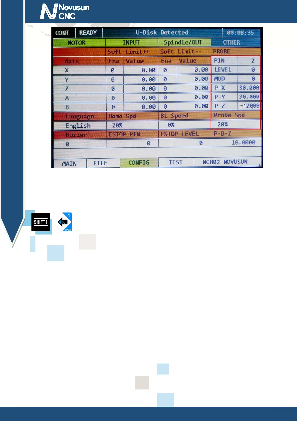
Figure4-6.
Probe configuration
in fixed-point probe mode
After the configuration is completed, we enter the main page and move the spindle to any
position. (we suggest that the Z axis of the tool tip is higher than the plane of the tool sensor). Press
+ , the system starts automatic probe. At this moment, the system will automatically
move to the location of the set of tool sensor to automatically probe. After the probe is finished, the
system will automatically return to the just start position of the probe.
4.2.2 Floating-point probe
The floating probe means that the location of the tool sensor is not fixed at a certain
location, but is placed in any desired location. In this mode, we usually place the tool sensor on
the workpiece surface for floating-point probe. The position of the tool sensor is placed in
reference figure 4-8.
In the floating tool mode, there is no need to configure the position of the tool sensor. We
enter the OTHER subpage under CONFIG and set the probe related settings as shown in Table
4-2. Floating-point probe configuration item screenshot reference figure 4-7.
www.nvcnc.net
 Loading...