77
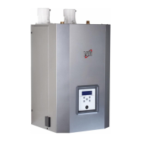
automatically. This seven (7) minute cycle
removes excess air from the CH and DHW systems.
a. During the cycle open the manual air vent
within the boiler. Close the air vent when clear
water free of air is visible (after purging).
b. As air is purged boiler pressure may drop. The
boiler needs to maintain at least 12-15 psi for proper purging.
NOTE: The water pressure switch safety is set at 8 psi to protect the
boiler. Error 108 will occur if boiler pressure drops too low. After
pressure is restored Error 108 will clear and the boiler will return to the
purge function for another 7 minutes.
c. After the cycle has ended ensure the system is completely purged
of air and verify that system pressure is at least 12 psi on the pressure
gauge. If not, repeat the procedure.
d. The purge function can be accessed at any time by pressing ESC for
ve (5) seconds. Press ESC to exit.
A. First Ignition
1. Make sure that the gas valve is closed and the electrical connections
have been properly wired and grounded.
2. Ensure that the system pressure is at least 12 psi on the tridicator
and no hot water or heating requests will be made.
NOTE: It is recommended to ll and purge the entire system before
powering the boiler.
3. Power on the boiler (press the ON/OFF button).
4. The boiler air purge function starts
NOTE: It is recommended to run through the full initial purge cycle at
install. Do not cut the purge cycle short.
5. The exhaust vent piping for combustion products should be suitable
and free from any obstructions.
6. Any necessary ventilation inlets in the room should be open (power
vent installation).
7. Set the room thermostat to the highest setting to start the boiler
and test Lockout Error 501.
NOTE: The boiler will display a Lockout Error 501 after the 3rd
consecutive failed ignition attempt.
- The combustion fan will pre-purge for a short time before activating
the igniter.
- Ensure the combustion fan post-purges for at least 5 seconds before
reactivating the igniter.
- After the boiler displays Error 501, set the room thermostat to the
normal setting to start the boiler.
8. Open the gas valve and check the connection seals, including the
boiler connection seals. Check for and eliminate any leaks.
9. Press the RESET button to clear Error 501. The display will show OK.
10. Start the boiler by selecting CH or DHW operation.
11. Proceed with Combustion Checking Procedure.
FOR YOUR OWN SAFETY READ BEFORE OPERATING
1. This boiler does not have a pilot. It is equipped with an ignition
device which automatically lights the burner. Do not try to light
the burner by hand.
2. BEFORE OPERATING: Smell all around the boiler area for gas.
Be sure to smell next to the oor because some gas is heavier
than air and will settle on the oor.
3. WHAT TO DO IF YOU SMELL GAS
• Do not try to light any boiler.
• Do not touch any electric switch, do not use any phone in
your building.
• Immediately call your gas supplier from a neighbor’s phone.
Follow the gas suppliers’ instructions.
• If you cannot reach your gas supplier, call the re
department.
• Turn off the gas shutoff valve (located outside the boiler) so
that the handle is crosswise to the gas pipe. If the handle
will not turn by hand, don’t try to force or repair it, call a
qualied service technician. Force or attempted repair may
result in a re or explosion.
4. Do not use this boiler if any part has been under water.
Immediately call a qualied service technician to inspect the
boiler and to replace any part of the control system and any gas
control that has been damaged.
5. The boiler shall be installed so the gas ignition system
components are protected from water (dripping, spraying, rain,
etc.) during boiler operation and service (circulator replacement,
condensate trap, control replacement, etc.)
Failure to follow these instructions could result in property
damage, serious personal injury, or death.
If you discover any evidence of a gas leak, shut down the boiler
at once. Find the leak source with a bubble test and repair
immediately. Do not start the boiler again until the leak is
repaired. Failure to comply could result in substantial property
damage, severe personal injury, or death.
WARNING
Part 11 - Start-Up
B. Combustion Checking Procedure
The order of operations for this procedure
must always be respected.
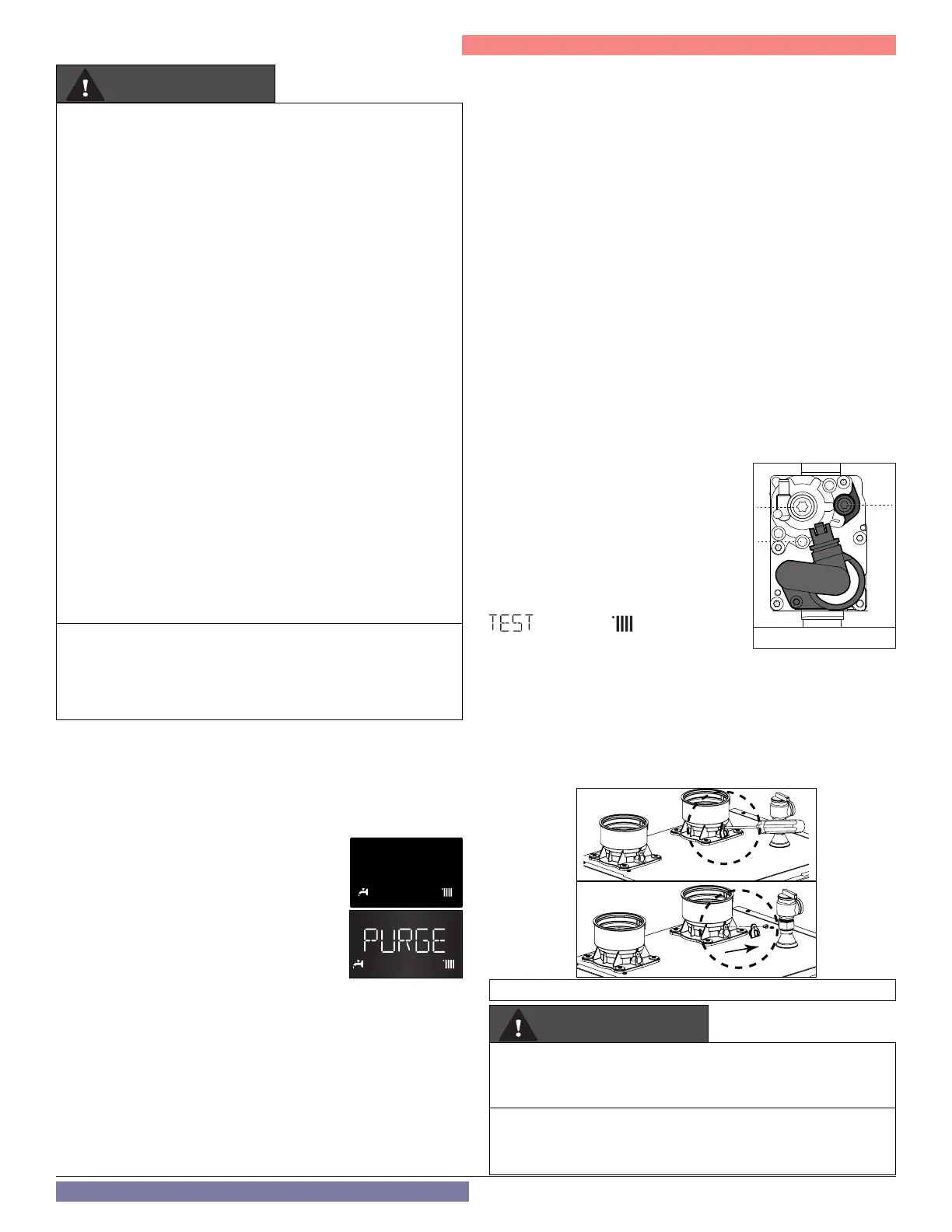
Operation 1 - Gas inlet pressure check
Loosen screw 1 (Torx 10 - Line Pressure Test
Port) and connect a manometer to the port
using applicable tubing.
Ensure the boiler is powered on. Then
enable Test Mode by pressing the RESET
button for 10 seconds. The display will show
and the icon .
The gas line pressure must remain within the
range provided in Table 21 for the gas type
during all operating conditions. Upon completion of the combustion
analysis and adjustment (Operations 2 through 5), remove the pressure
gauge and tighten screw 1. Verify and repair any gas leaks.
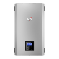
Operation 2 - Combustion Analysis
Remove the combustion test port plug as illustrated, and insert a
calibrated combustion analyzer.
4
2
1
Figure 73 - Gas Valve
Figure 74 - Combustion Test Port
Make sure the calibrated combustion analyzer is set to the
appropriate gas type. Failure to do so could result in serious
personal injury or death.
It is required to use a calibrated combustion analyzer to verify
nal adjustment according to the combustion chart (Table 30).
Failure to do so could result in serious personal injury or death.
WARNING