92
Part 1 - General Safety Information
Part 14 - Maintenance
Ensure that the correct gas diaphragm and mixer are used for
the correct fuel type for the boiler - Natural Gas or Propane. See
Conversion Kit Instructions. Failure to do so will result in substantial
property damage, severe personal injury, or death.
DANGER
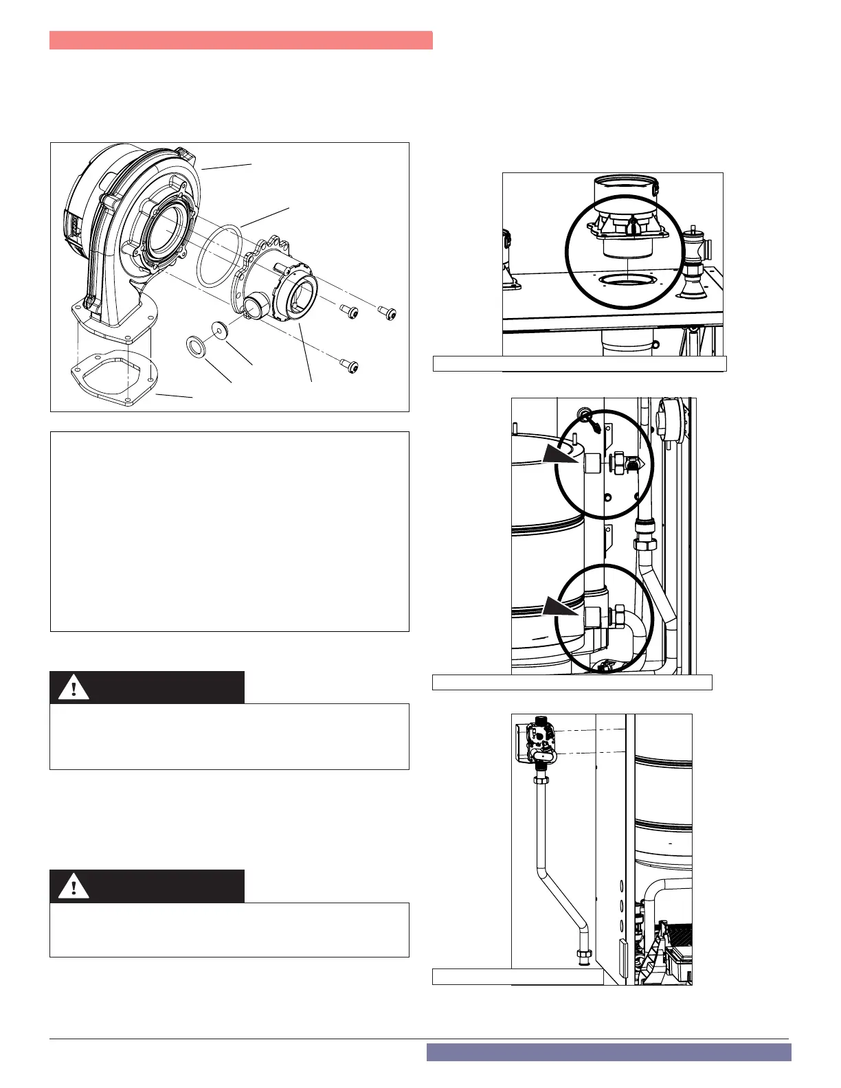
Replacing the Fan
1. Remove the silencer and gas line as described in Cleaning the Heat
Exchanger Combustion Chamber.
2. Loosen the three [3] screws to release the Mixer (1) from the fan (5).
Ensure the O-Ring (4) is not damaged or deteriorating.
4
5
1
2
6
3
Legend:
1 - Mixer(when converting to
Propane, install the Mixer
included in the Natural Gas
to Propane Conversion Kit)
2 - Gas Diaphragm if applicable
(FTVN150 / FTVN150C
Natural Gas Models include
a Gas Diaphragm. All Models
converted to Propane
require a Gas Diaphragm -
see Natural Gas to Propane
Conversion Instructions)
3 - Gas Seal
4 - O-Ring
5 - Fan
6- Fan to Top Plate Gasket
3. Depending on the model, loosen the three [3] or four [4] screws to
release the fan from the heat exchanger.
Figure 89 - Removed Fan, Mixer, and Components
4. Reassemble the mixer and fan assembly in the reverse order. Ensure
the O-Ring (4) is installed between the mixer and fan.
5. Reinstall the fan and combustion assembly components as
described in Cleaning the Heat Exchanger Combustion Chamber.
Ensure the gasket (6) is assembled between the fan and air inlet
channel.
Failure to replace damaged or deteriorating gaskets or O-Rings will
result in exhaust gas leaks, substantial property damage, severe
personal injury, or death.
DANGER
Replacing the Main Heat Exchanger
1. Drain the boiler and remove the combustion assembly as
described in Cleaning the Heat Exchanger Combustion
Chamber.
2. Remove the combustion assembly as described in Cleaning the
Heat Exchanger Combustion Chamber.
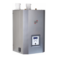
3. Remove the exhaust vent adapter on the top of the boiler.
4. Disconnect the CH supply and return pipes.
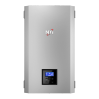
5. Remove the gas pipe.
Figure 90 - Remove the exhaust vent adapter
Figure 91 - Remove the CH Supply and Return Pipes
Figure 92 - Remove the Gas Pipe