93
Part 1 - General Safety Information
Part 14 - Maintenance
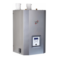
7. Remove the electrical junction box.
Figure 94 - Remove the Heat Exchanger
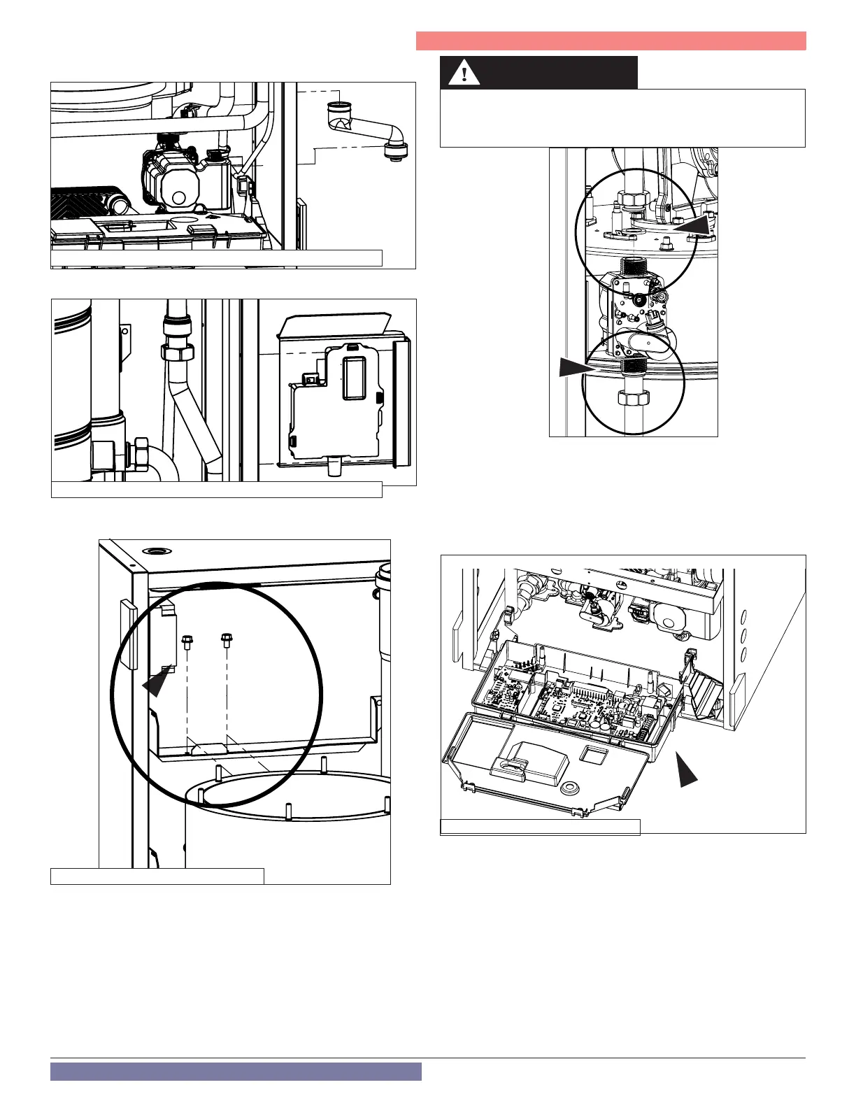
Figure 93 - Remove the Condensate Pipe
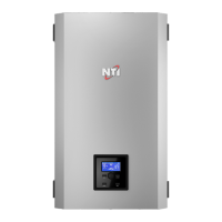
Figure 95 - Disconnect the Gas Valve
Failure to replace the sealing rings will result in gas leaks, and could
cause an explosion or re, substantial property damage, severe per-
sonal injury, or death.
DANGER
Replace the Main PCB
1. Fold down the electronics box.
2. Unlock the two clips and open the electronics box cover.
3. Disconnect the electrical connections.
4. Unhook the controller board and remove it.
5. Proceed in reverse order to install the new PCB.
6. Follow the instructions provided with the replacement PCB kit for
setting all necessary parameters.
Figure 96 - Disconnect the Main PCB
6. Disconnect the condensate line.
Figure 97 - Remove the Junction Box
8. Remove the bolts mounting the heat exchanger to the cabinet.
9. Proceed in the reverse order to install the new heat exchanger.
Replacing the Gas Valve
1. Remove the electrical connection from the gas valve.
2. Remove the two (2) nuts above and below the gas valve.
3. Remove the two (2) screws securing the gas valve to the bracket.
4. Remove the gas valve.
5. Reinstall the new gas valve in reverse order.
6. BE SURE TO USE NEW SEALING RINGS.
7. Ensure there are no gas leaks.