78
Part 11 - Start-Up
Operation 3 - Adjusting the CO2 at Maximum Gas Flow Rate (High
Fan Speed)
Set the thermostat at the highest possible setting or draw o the
domestic hot water at the maximum water ow rate to create a
demand for heat. Note: For only Heating Boiler Applications, open all
thermostatic valves present in the CH circuit.
Select the TEST Function by pressing and holding the RESET button for
10 seconds.
WARNING! When the Test Function is activated the temperature of
the water coming out of the boiler may be more than 150°F.
and the icon will appear on the display
when Test Function is active. The boiler will operate
at maximum heating power.
Press the button to operate
the boiler at the maximum power.
The icon will display.
Wait 1 minute for the boiler to
stabilize before carrying out the
combustion analyses. Read the
CO2 value (%) and compare it
with the values given in the table
below:
Natural Gas LP Gas
Fan Speed Low High Low High
CO PPM <175 <175
CO2 (%) 8.5 - 10.0 9.5 - 11.0
ATTENTION: The CO2 at minimum gas ow (Low Fan Speed) must
not be set higher than the CO2 reading at maximum gas ow
(High Fan Speed). It may be set lower by as much as 1.0%.
For Example: If CO2 at Max. = 9.5%, CO2 at Min. = 8.5-9.5%
Table 30 - Combustion Settings
ATTENTION!! Obtain all values with the front cover installed.
If the CO2 (%) reading diers from the values given in the table, adjust
the gas valve following the instructions below. Otherwise move
directly to Operation 4.
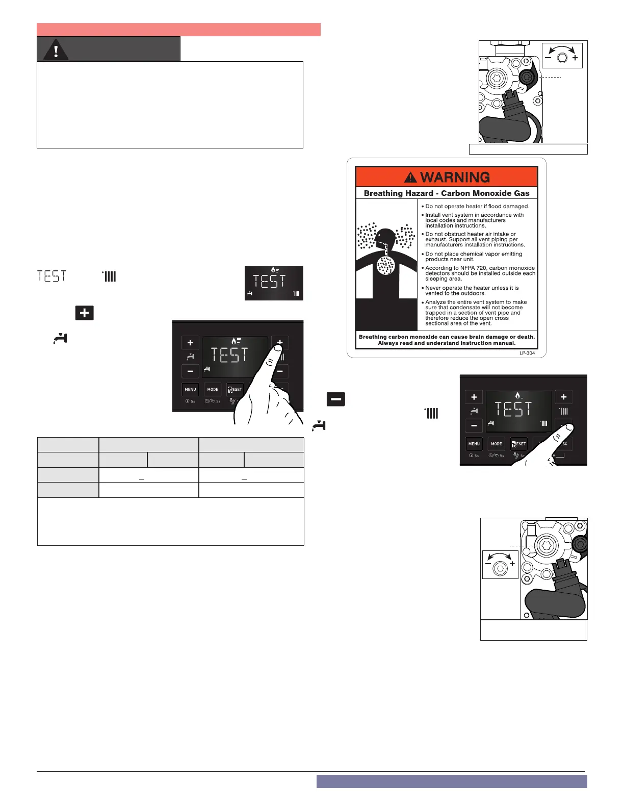
Adjusting the Gas Valve at Maximum Gas Flow
Adjust the gas valve by turning setting screw 4 clockwise to increase
the CO2 level; counterclockwise to reduce the CO2 level (1 turn adjusts
the CO2 level by approximately 0.3%). Wait 1 minute after each change
in setting for the CO2 value to stabilize.
4
Figure 75 - Max CO2 Adjustment
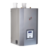
It is very important that the combustion system be set within
the recommended CO measurements listed in Table 30. Visually
looking at the burner does not determine combustion quality.
Failure to measure combustion with a calibrated combustion
analyzer and set the throttle within the recommended CO
measurements could result in property damage, severe personal
injury, or death.
WARNING
If the value measured corresponds to
the value given in the Table 30, max
adjustment is complete. Otherwise
continue the setting procedure.
ATTENTION!! The Test Function will
automatically deactivate after 30 minutes,
or Test Function can be turned o manually
by pressing the RESET button.
Operation 4 - Checking the CO2 at Minimum Gas Flow (Low Fan
Speed)
With the Test Function active, press
the button to operate the boiler
at minimum DHW power. The and
icons will display.
Wait 1 minute for the boiler to
stabilize before carrying out the
combustion analyses.
If the CO2 (%) reading at min gas ow
is greater than the CO2 (%) reading at max ow, or if it is less than the
reading at max ow by more than 0.3%, adjust the gas valve following
the instructions below. Otherwise move directly to Operation 5.
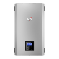
Adjusting the Gas Valve at Minimum
Gas Flow
Remove
cap and adjust screw 2 by turning
counter-clockwise to reduce the CO
2
level;
clockwise to increase the CO
2
level. Wait 1
minute after each adjustment for the CO
2
value to stabilize.
WARNING! Minimum Gas Flow
Adjustment is very sensitive.
If the value measured corresponds to
the value given in Table 30 adjustment is
complete. Otherwise continue the setting procedure.
Attention!! If the value of the CO
2
at minimum power has been
changed, it is necessary repeat the adjusting at maximum gas ow.
Operation 5 - Ending Adjustment
1. Exit Test Mode by pressing RESET.
2. Turn down the thermostat and / or stop the DHW draw-o. For Only
Heating Boiler applications reset all thermostatic valves.
3. Check for and repair any leaks of gas.
4. Reinstall the front cover.
5. Reinstall the combustion test port - see Figure 74.
2
Figure 76 - Min CO
2
Adjustment