Display System Utilization
en-938821/2 4 - 21
4
4.6.3 3D Display
The 3D display shows parts in isometric projection.
It is used to:
- visually check the shape of a part (or section of a part) from different angles using a rotation function,
- display details in cross-section.
The 3D display function can display cross-sections of a part in isometric projection.
In order to use the 3D display function, a rectangular block corresponding to the blank must first be declared in the
programme (See Programming manual). Reminder: the rectangular block is declared using the following syntax: "EM+
X.. Y.. Z.. EM- X.. Y.. Z.." (the dimensions after EM+ are the maximum dimensions of the parallelepiped and the
dimensions after EM- are the minimum dimensions).
Only simple-shaped cutters are used (cylindrical, toroid or spherical and drills).
Requirements
Graphic display parameters page displayed and programme selected.
Declaration of blank in the programme.
Tool data declared in the tool correction table.
Actions
Select the 3D display function. ☞
3D
MODEL
Display of the 3D display selection softkeys at the bottom of the screen:
Q - R -
128
RESOLU
3D
MODEL
256
RESOLU
P + Q + R +
EXIT
P -
Select the desired resolution (default value: 256). ☞
128
RESOLU
or
256
RESOLU
The softkey corresponding to the desired resolution is depressed. The resolution of 256 provides higher precision
during the trace functions than the resolution of 128 but requires more processing time.
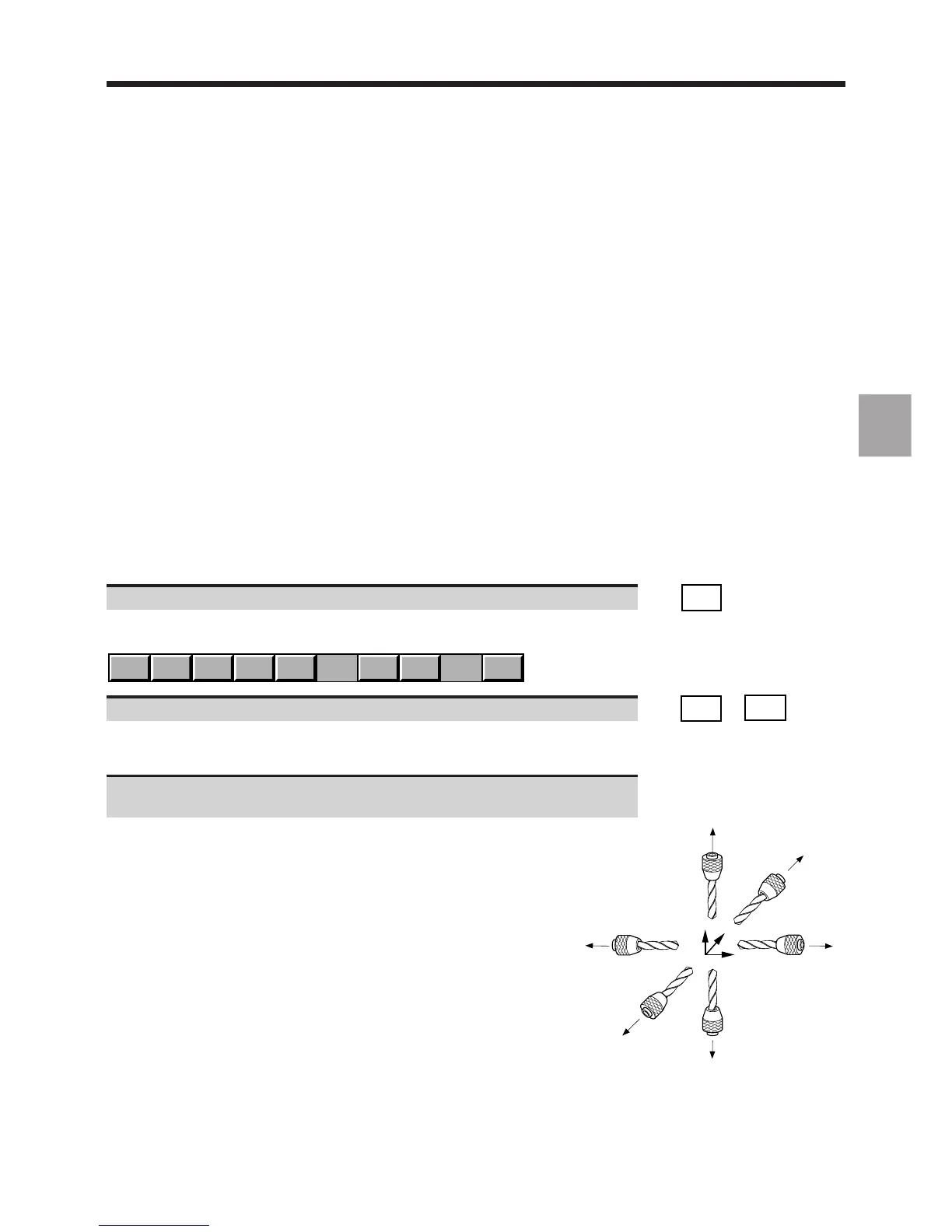
Select the tool orientation (See diagram) used in the programme
(default setting: R+).
The softkey corresponding to the tool orientation is depressed.
In a programme, the tool orientation is defined by the arguments of
function G16 (See Programming manual).
The diagram opposite summarises the tool orientations and associated
arguments of G16.