Table of Contents
1. Introduction ........................................................................................................................................................................ 3
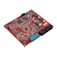
2. LCEVB Features ................................................................................................................................................................... 3
2.1. Differences to the Customer EVB ............................................................................................................................... 4
3. Configuration Overview ...................................................................................................................................................... 6
4. Initial Setup ......................................................................................................................................................................... 7
4.1. Power Supply Configuration ....................................................................................................................................... 7
4.1.1. Power Input Connector ..................................................................................................................................... 7
4.1.2. Power Switch ..................................................................................................................................................... 7
4.1.3. Power Status LED ............................................................................................................................................... 8
4.1.4. MCU and Peripheral Voltage Configuration ...................................................................................................... 8
4.2. Reset Control (SW3) ................................................................................................................................................... 8
4.2.1. Reset LEDs ......................................................................................................................................................... 9
4.3. MCU Clock Configuration ......................................................................................................................................... 10
4.4. Debug Connector (P1) .............................................................................................................................................. 10
4.4.1. Debug Connector Pinout ................................................................................................................................. 10
5. Communications & Memory Interfaces: ........................................................................................................................... 11
5.1. CAN Interfaces (P2, P3) ............................................................................................................................................ 11
5.2. LIN Interfaces (P6, P7) .............................................................................................................................................. 12
5.3. USB RS232 Serial Interface (P11) .............................................................................................................................. 12
5.4. USB HOST Interface (P4)........................................................................................................................................... 12
5.5. Ethernet Interface (P5) ............................................................................................................................................. 13
5.6. FlexRay (P8, P9, P10) ................................................................................................................................................ 13
6. User Interface (I/O) ........................................................................................................................................................... 14
6.1. GPIO Matrix .............................................................................................................................................................. 14
6.2. User Switches (SW4, SW5) ....................................................................................................................................... 15
6.3. Hex Encoded Switch (SW1) ...................................................................................................................................... 15
6.4. User LED’s (DS1, DS2, DS3, DS4) ............................................................................................................................... 16
6.5. ADC Input Potentiometer (RVAR, RV1) .................................................................................................................... 16
7. MCU Port Pin LCEVB Functions ......................................................................................................................................... 17
8. Appendix ........................................................................................................................................................................... 18
9. Revision History ................................................................................................................................................................. 34
MPC5748G Low Cost EVB User Guide, Rev. 1, 08/2016
2 NXP Semiconductors
Downloaded from Arrow.com.Downloaded from Arrow.com.