6. User Interface (I/O)
This section details the user I/O available on the LCEVB and includes the GPIO matrix, switches,
LED’s and the ADC variable resistor.
6.1.
GPIO Matrix
The GPIO matrix is
on the right hand
edge of the LCEVB
A sub-set of available GPIO pins (available pins being those not already routed to LCEVB peripherals)
are available at the GPIO matrix as detailed below. The matrix provides an easy to follow, intuitive,
space saving grid of 0.1” header through-hole pads. Users can solder wires, fit headers or simply insert a
scope probe into the respective pad.
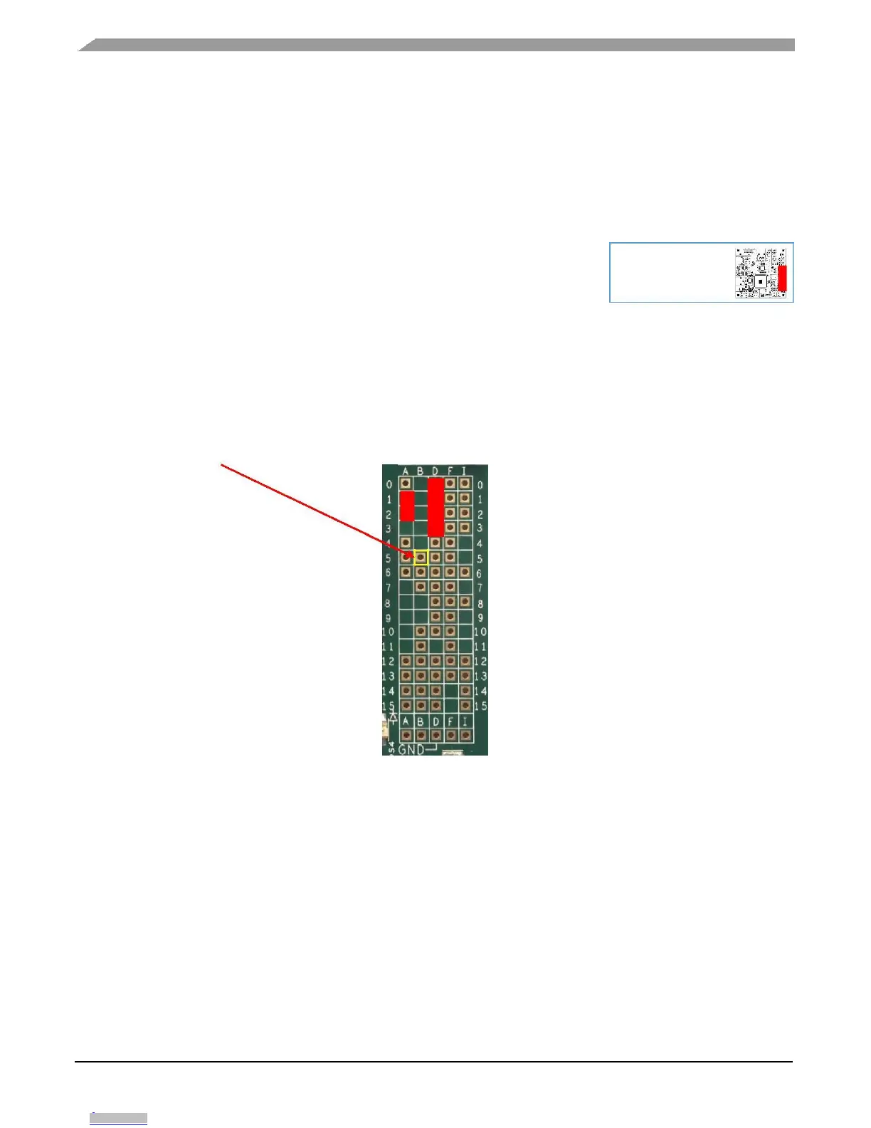
To use the matrix, simply read the port letter from the top or bottom row of text then the pad number
from the columns on the left or right of the matrix. For example, the 1
st
pad available on Port B is
PB5 as outlined below.
Figure 7. GPIO Matrix
If a pad is populated in the matrix, it means this is available for exclusive use as GPIO. The exception
to this are the port pins detailed below which are also shared with switches or user LED’s (shaded red in
the matrix diagram above).
PD0, PD1, PD2, PD3 – HEX Encoder Switch
PA1, PA2 – User pushbutton Switches
If you require access to all of the available GPIO pads, the customer EVB and daughter card
provides this additional functionality.
MPC5748G Low Cost EVB User Guide, Rev. 1, 08/2016
14 NXP Semiconductors
Downloaded from Arrow.com.Downloaded from Arrow.com.Downloaded from Arrow.com.Downloaded from Arrow.com.Downloaded from Arrow.com.Downloaded from Arrow.com.Downloaded from Arrow.com.Downloaded from Arrow.com.Downloaded from Arrow.com.Downloaded from Arrow.com.Downloaded from Arrow.com.Downloaded from Arrow.com.Downloaded from Arrow.com.Downloaded from Arrow.com.