Initial Setup
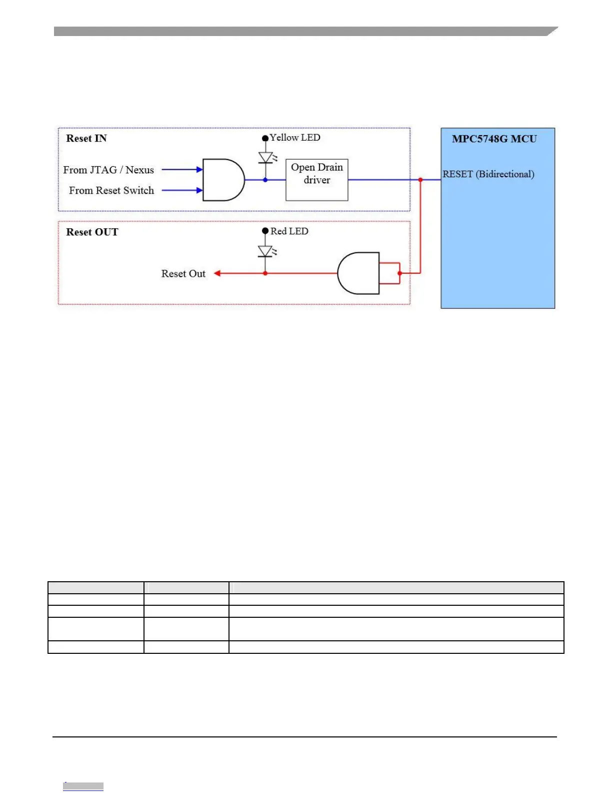
This scheme is not required if it is guaranteed that anything driving the reset pin has an open drain
drive and that there is no significant output load on the MCU reset pin.
Figure 4. EVB Reset Control
4.2.1.
Reset LEDs
As can be seen above, there are two reset LED’s that can be used to identify the source / cause of a reset:
RED LED DS8 (titled “MCU”) will illuminate if:
The MCU issues a reset (in this condition ONLY this LED will be illuminated and LED
DS1 will be off)
There is a target reset (i.e. from the reset switch or from the debugger in which case LED
DS1 will be ON)
YELLOW LED DS7 (titled “EXT”) will illuminate when an external hardware device issues a reset
to the MCU:
The reset switch is pressed
There is a reset being driven from one of the debug connectors
Table 2. Reset LED Decoding
No Reset being issued from MCU or external logic
External reset issued from switch or debug BUT not being issued to MCU
(check R137 has not been removed)
External reset issued from reset switch or debug and has been issued to MCU.
MPC5748G Low Cost EVB User Guide, User Guide, Rev. 1, 08/2016
NXP Semiconductors 9
Downloaded from Arrow.com.Downloaded from Arrow.com.Downloaded from Arrow.com.Downloaded from Arrow.com.Downloaded from Arrow.com.Downloaded from Arrow.com.Downloaded from Arrow.com.Downloaded from Arrow.com.Downloaded from Arrow.com.