Chapter 4 43
Installation
7. Locate the troughs on the top and bottom of the auxiliary EPC manifold
connector block and the ridges in the pneumatics carrier compartment. Slide
the auxiliary EPC manifold into the carrier compartment, lining up the ridges
and troughs. From the front of the GC, secure the auxiliary EPC manifold in
place by tightening the captive Torx T-20 screw.
8. Plug the auxiliary EPC manifold’s ribbon cable into the auxiliary connector
facing upward on the electronics board, and push it until the lug is firmly in
place. Lock the connector by moving the tabs to the center of the connector
until they click into place. (See the Agilent 6890 GC Auxiliary Pressure
Control Manifold Installation Guide for further instruction.)
9. Remove the protective caps from the AUX 3 (H
2
), AUX 4 (Air 1), and AUX 5
(Air 2) gas inlet connectors on the front of the auxiliary EPC manifold (see
Figure 4.10).
10. Connect the regulated H
2
gas supply to the AUX 3 connector using a Q/i" nut
and ferrule (see Figure 4.10).
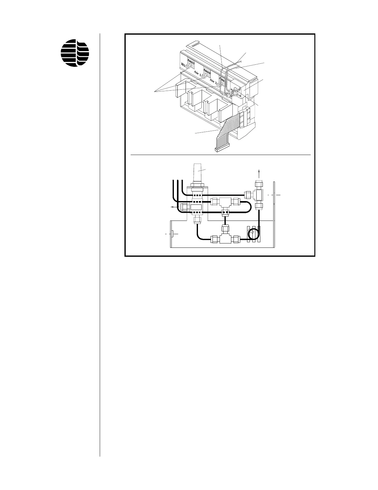
Figure 4.10. Auxiliary EPC Manifold and Aux EPC Pneumatics Kit
COMB
WALL
COMB
Gas Out
Gas Lines
WALL
Gas Out
Ribbon Cable
Gas Inlets
Gas Outlet Block
#251900
Outlet Block Screw
#185561
Air 2 Gas Line
Air 1 Gas Line
H
2
Gas Line
Fine Adjust
Needle Valve
3 4 5
3 = H
2
4 = Air 1
5 = Air 2