2 Model 5380 PFPD Operator’s Manual
Rev. 3.1
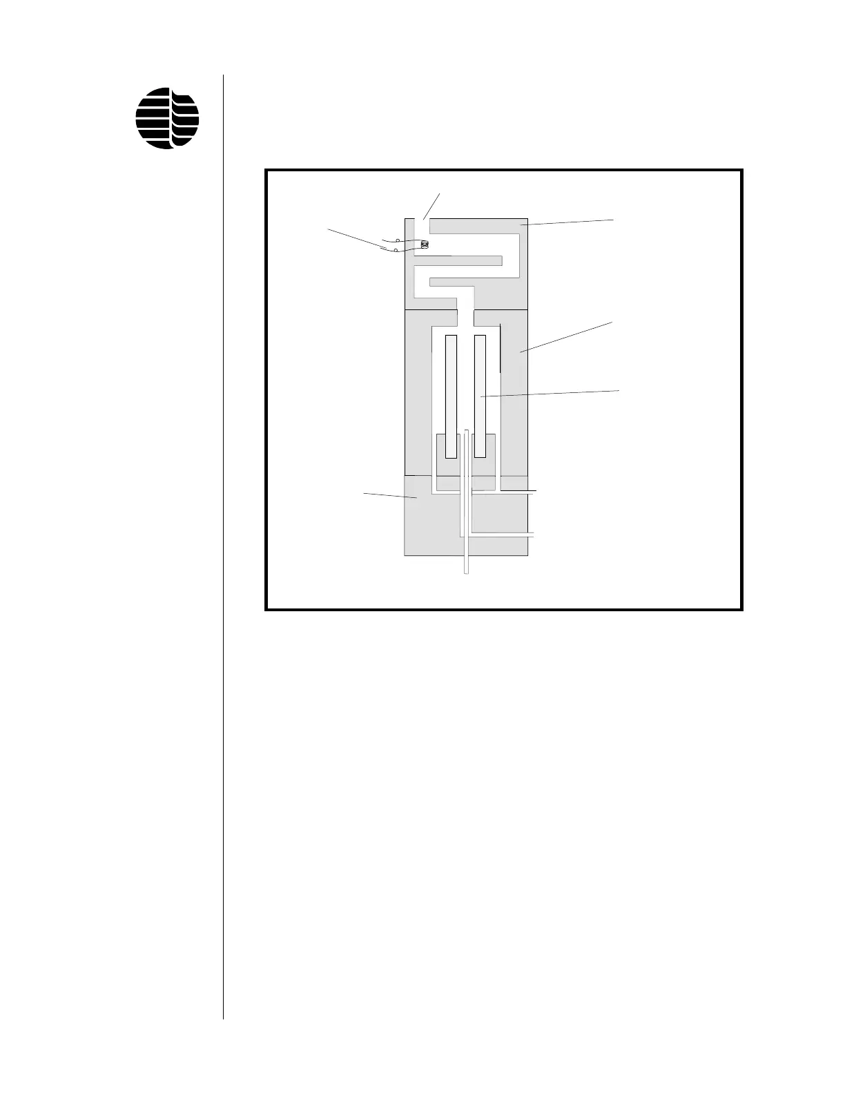
gas mixture, which is richer with air for easier ignition. The primary and secondary
gas flows are known as combustor gas (COMB) and wall gas (WALL), respec-
tively. The separate pathways of these two gas mixtures within the detector are
shown schematically in Figure 1.1.
The pulsed flame propagation consists of a four phase cycle: replenishment of
combustible gases, ignition of gases, downward propagation of the flame (combus-
tion), and extinction of the flame (see Figure 1.2). The cycle begins with the
combustor gases (GC effluent, H
2
, and air) flushing out the combustor. Simulta-
neously, the wall gases (H
2
and air) sweep spent gases from the ignitor region
through a vent, and fill this space with a combustible gas mixture. The flame is
initiated when this gas mixture reaches the glowing ignitor coil. The flame then
propagates from the ignitor region through a convoluted pathway (to prevent light
from the ignitor reaching the PMT) and down into the combustor. If the gas
composition within the combustor is set correctly, the flame continues to propagate
toward the bottom of the combustor, where it terminates when all the combustor
gas has been consumed.
The pneumatic system of the PFPD has been designed to allow the operator to
regulate both the flow rates and the H
2
:Air composition of the combustor and wall
gases. Figure 1.3 provides a flow diagram of the pneumatic system. Three manual
or electronic gas flow controllers enable the operator to adjust the flow rates of H
2
and air in the combustor gas and wall gas mixtures. The H
2
and Air 1 control
Figure 1.1. Combustor and Wall Gas Pathways
Ignitor
Vent
Detector Cap
Detector Body
Combustor
Detector Base
Combustor Gas
(H
2
+ Air 1; H
2
rich)
Wall Gas
(H
2
+ Air 1 + Air 2;
Air rich)
GC Effluent
↑
←
←