Chapter 1 3
Introduction
valves determine the composition of the gas mixture supply to the combustor. In
order to achieve rapid and consistent flame initiation at the ignitor, additional air is
added to the wall gas mixture by adjusting the Air 2 control valve. The relative
amounts of the H
2
:Air 1 gas mixture that flow to the combustor and ignitor regions
are controlled by a fine adjust needle valve.
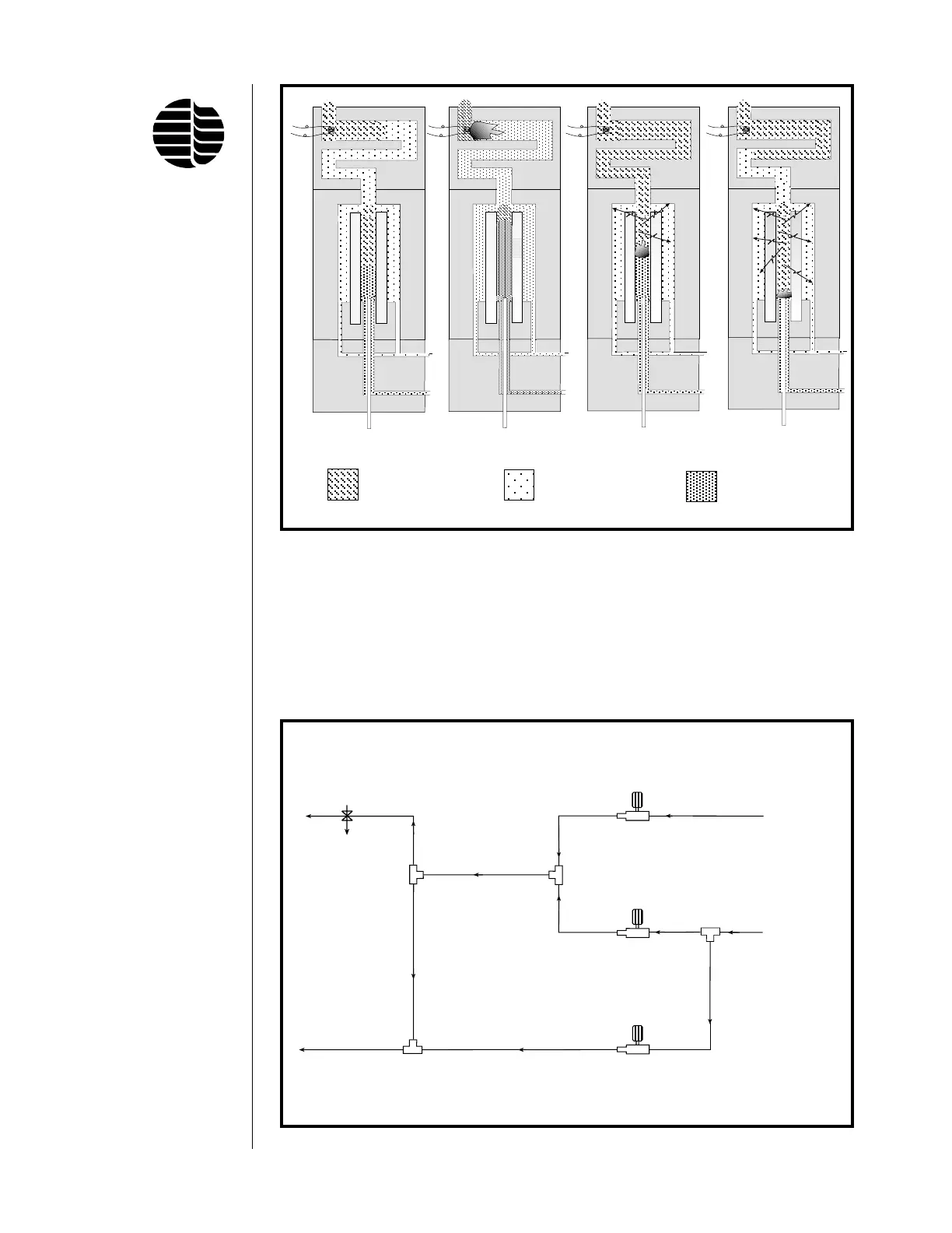
Figure 1.2. Four Phase Cycle of Propagating Flame
Replenishment
Ignition
Combustion
Extinction
Gas Outlets
Combustor Gas (COMB)
(H
2
+ Air 1; H
2
rich)
connects to lower gas line on detector base
Manual or Electronic
Gas Flow Regulators
Supply
Gas Inlets
H
2
Air 1
Air 2
H
2
IN
Air IN
Wall Gas (WALL)
(H
2
+ Air 1 + Air 2; Air rich)
connects to upper gas line on detector base
T3
T2
T1
T4
Figure 1.3. Model 5380 PFPD Pneumatics Flow Chart
Spent Gas Wall Gas Combustor Gas