4 Model 5380 PFPD Operator’s Manual
Rev. 3.1
In general, the gas flow controllers are used to optimize the H
2
:Air ratios in both
the wall and combustor regions while the fine adjust needle valve is used to
regulate the split of the H
2
:Air 1 mixture between the wall and combustor regions.
The relative rates of the wall and combustor flows can be adjusted so that the time
required to fill the ignitor volume with gas is equal to or slightly greater than the
time required to fill the combustor. If the ignitor fill time is less than the combustor
fill time, flame propagation becomes unstable with the flame alternately terminat-
ing at the top and the bottom of the combustor. This phenomenon is known as
“tick-tock.” Combustion of the GC analyte within the combustor volume is opti-
mized by using the fine adjust needle valve to adjust the detector to the tick-tock
condition and then increasing the combustor flow (or decreasing the ignitor flow)
slightly until the flame terminates only at the bottom of the combustor. This allows
the operator to easily manipulate the kinetics of the propagating flame and the
associated magnitude and lifetime of the chemiluminescence resulting from
combustion. (Refer to Chapter 5, “Operation,” for a discussion of pneumatic
settings that optimize the operating efficiency of the PFPD.)
The emission spectra detected by the PFPD are the product of the transmission of
the emitted photons through the light pipe and filter, and the spectral sensitivity of
the photomultiplier tube. Specific emission bands can be observed for species that
are produced in the PFPD. With a conventional flame photometric detector (FPD),
narrow band pass or interference filters are used to minimize interference from
carbon in the continuous flame. By contrast, the PFPD uses broad band pass filters
and time-based selectivity to minimize interference and increase optical through-
put. The background emission associated with the H
2
-rich flame in the combustor
consists of CH*, C
2
*, and OH* species that exist in the flame. While this emission
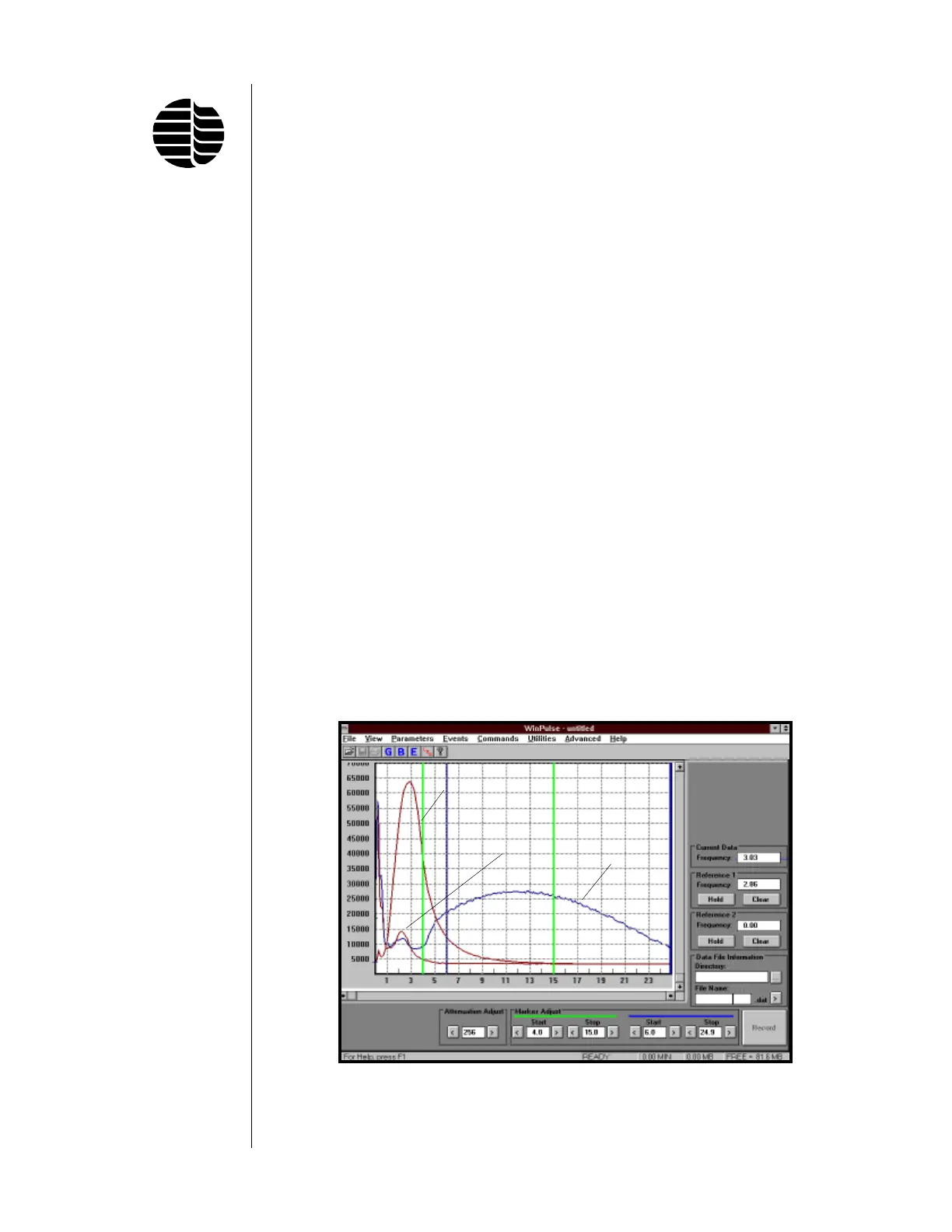
lasts less than 1 ms, the observed emission time of up to 4 ms (Figure 1.4) is due to
the dynamics of the flame propagating through the combustor. However, the sulfur
emission reaches its maximum 5–6 ms after the background emission is nearly
terminated. Thus sulfur and phosphorus have chemiluminescence lifetimes sub-
Figure 1.4. Carbon, Phosphorus, and Sulfur Emission Lifetimes
Sulfur
Phosphorus
Carbon