45850101TH Rev.1
4-16
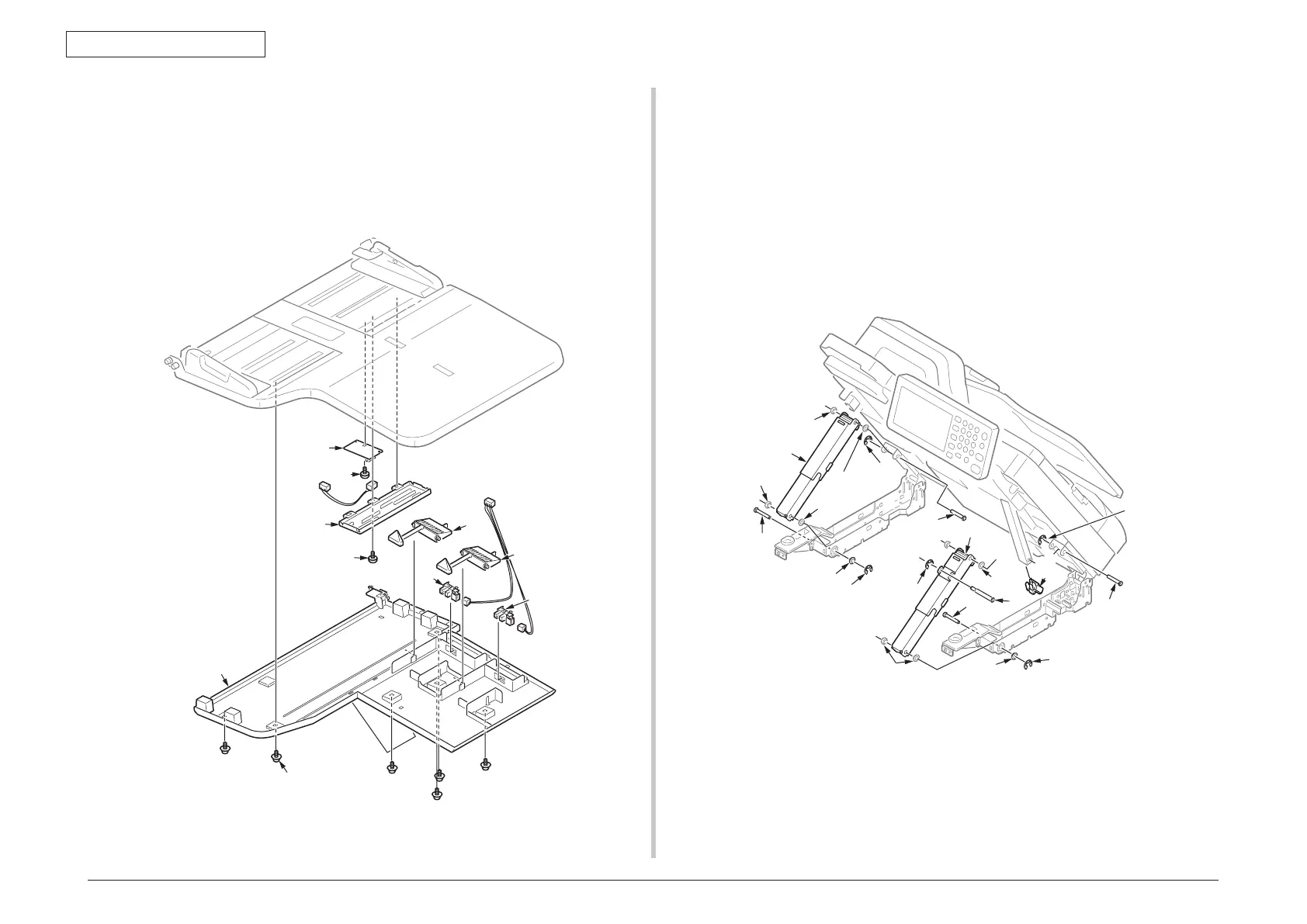
4.2.10.2 Tray-Assy-Document
(1) Remove the six screws (black, No:42932708)
①
and Cover-Tray-document
②
.
(2) Remove the Lever-Tray
③
and photo-sensor
④
.
(3) Remove a screw (silver, No:42933005)
⑤
and Plate-Detection(Tray)
⑥
.
(4) Remove a screw (silver, No:42933005)
⑦
and Board-tray
⑧
.
②
③
④
④
⑤
⑥
⑦
①
×6
③
⑧
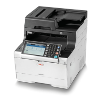
4.2.10.3 Damper Assy-L/R
(1) Remove the scanner unit. (See to 4.2.10)
(2) Remove the three E-type retaining ring
①
and bearing
②
, and remove a Cap.
(3) Remove the shaft
③
,
④
,
⑤
and Damper Assy-R
⑥
.
(4) Remove the two E-type retaining ring
⑦
and bearing
⑧
.
(5) Remove the shaft
⑨
,
⑩
and Damper Assy-L
⑪
.
Note! When the shaft
③
,
⑤
,
⑨
,
⑩
would be removed from each the Damper
Assy, note the any bearings not droppin. These bearings are arranged to the
both side of Damper Assy at each shafts.
Bearing
Bearing
ing
Bearing
Bearing
Bearing
③
①
④
⑤
⑥
Ⓐ
Ⓑ
Ⓑ
Ⓐ
①
⑩
⑪
⑨
⑦
⑧
⑦
Cap