5
Table of figures
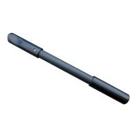
Figure 4.1: Elements of the electrodes ................................................................................................... 20
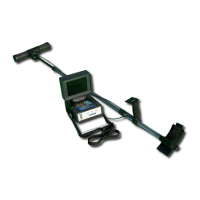
Figure 4.2: Elements of the power cable drums ..................................................................................... 21
Figure 4.3: Elements of the voltage cable drums .................................................................................... 22
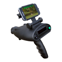
Figure 4.4: Control elements of the Controller ....................................................................................... 23
Figure 4.5: Elements of the tablet holder ............................................................................................... 24
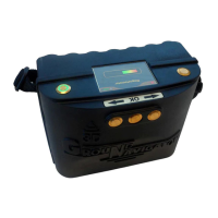
Figure 4.6: Control elements of the Power Box ....................................................................................... 25
Figure 5.1: Installation of the application via Google Play Store ............................................................ 28
Figure 5.2: Application's main menu ...................................................................................................... 29
Figure 5.3: New Measurement - Creation process .................................................................................. 30
Figure 5.4: New Measurement - Project title / notes .............................................................................. 30
Figure 5.5: New Measurement - Scan mode ........................................................................................... 31
Figure 5.6: New Measurement - Scan profile ......................................................................................... 31
Figure 5.7: New Measurement – Depth settings ..................................................................................... 32
Figure 5.8: New Measurement - Field dimensions .................................................................................. 32
Figure 5.9: New Measurement - Arrangement of electrodes .................................................................. 33
Figure 5.10: Continue Measurement ...................................................................................................... 34
Figure 5.11: View Measurement – List of files ........................................................................................ 35
Figure 5.12: View Measurement - 3d representation .............................................................................. 35
Figure 5.13: Activation ........................................................................................................................... 36
Figure 5.14: Support Information ........................................................................................................... 37
Figure 6.1: Placing batteries into the Controller's compartments .......................................................... 40
Figure 6.2: Connecting the Controller's charger .................................................................................... 41
Figure 6.3: Tablet PC mounted to Controller .......................................................................................... 42
Figure 6.4: Voltage Cable Drums mounted to Controller ........................................................................ 42
Figure 6.5: Connecting the Power Box Charger ...................................................................................... 43
Figure 6.6: Enabling Wi-Fi ...................................................................................................................... 44
Figure 6.7: Entering Wi-Fi password ...................................................................................................... 45
Figure 7.1: Detection of thick objects is better than flat objects ............................................................ 48
Figure 7.2: Dividing the field into scan points and setting up markers ................................................... 49
Figure 7.3: Power injection depth depends on electrodes distance ........................................................ 50
Figure 7.4: Available Scan Modes ........................................................................................................... 50
Figure 7.5: Instruction screen for setting up a measurement ................................................................. 52
Figure 7.6: Arrangement of electrodes during Active Scan (Accurate) ................................................... 58
Figure 7.7: Arrangement of electrodes during Active Scan (Quick) ........................................................ 58
Figure 7.8: Arrangement of electrodes during Passive Scan .................................................................. 59
Figure 8.1: Measure values as indicated during a measurement ............................................................ 62
Figure 8.2: Graphical 3d representation of an active scan ..................................................................... 63
Figure 8.3: Graphical 3d representation of a passive scan ..................................................................... 64
Figure 8.4: Example of a passive measurement – flowing water ............................................................. 65
OKM GmbH
www.okmmetaldetectors.com