MAESTRO SMART
US-ENG- 7
US-ENGLISH
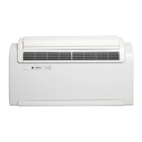
2.3 - CHOOSING THE POSITION OF THE UNIT (g.2-3)
The unit must be installed on a wall that directly communicates with the outside. The position for installing
the unit must have the following prerequisites:
• Theheightoftheunit’sloweredgefromtheoorshouldbeatleast4”(100mm)ifinstalledonthewall
in the lowest position.
• Ifinstalledonthewallinthehighestposition,itshouldbeatleast3.5”(90mm)fromtheceiling.
• Thewallonwhichtheinsideunitisinstalledmustbeofsufcientstrengthtowithstanditsweight.
• Theremustbeadequatespacearoundtheunitforanymaintenanceorservicethatmaybenecessary.
• Thereshouldbenothinginthewayoftheairthatneedstocirculatebothonthetopreturnair(curtains,
plants, furniture) or at the front where the air exits (supply air). this could cause air swirls that could effect
theunitperformanceandefciency.
• Itmustbepossibletoleaveroomaroundtheunitforanymaintenanceoperationsthatmaybenecessary.
When selecting the unit’s location as described above the installer must insure there are no
structures or systems (beams, piers, pipes, wires, etc.) at the points where the holes are to be
drilled. Interference from any item would prevent drilling the holes required to install the unit.
• Theunitshouldnotbeplacedundercurtainsthatmayblockfreemovementoftheair.
• Donotspraywaterorotherliquidsofanykinddirectlyontheunit.
• Theunitshouldnotbeinstalledinapositionwheretheairowisdirectedtowardsoccupantsinthe
conditioned space.
• Neverforceopenthesupplyairap.
• Donotplaceanyotherobjectontheairgrillethatmayevenpartiallyobstructthegrilleitself.
• Theunitshouldnotbeinstalleddirectlyoveranotherappliance,suchasatelevisionset,radio,refriger-
ator, etc., or over any other source of heat.
• Donotstoreanythingontheunitasitwilllimitairow,reducecapacityandincreaseenergycosts.
• Donotattempttomanuallyopenorclosethemodulatingdamperorspraycorrosivecleaningagents
into the unit.
• Donotallowcurtainsorotherhangingmaterialstoblocktheowofairenteringorexitingtheunit.
• Donotallowairowtobedirectedtowardsoccupantsastheircomfortwillbenegativelyimpacted.Also,
do not install the unit in close proximity to heat producing appliances or devices.
2.4 - UNIT ASSEMBLY
The maximum length allowed for the wall sleeves is 39” (990 mm). the wall sleeves must be smooth on the
inside with a diameter of 8” (200 mm). Wall sleeves cannot be curved or bent. it is strongly recommended
to use the louvred grilles provided, or if other grilles are to be used, they must be factory approved to
avoidcapacityorefciencyissuesdueinsufcientairow.
2.4.1 - DRILLING THE WALL (g.4-5-6)
Install the unit by drilling two holes (diameter of both pipes must be either 8”(200 mm) or 6.4”(160 mm)
through the wall as indicated on the drilling installation template. The 8”(200 mm) holes will ensure the best
performance and lowest air noise level. Drill the wall using the proper tools, taking care to prevent excess
damage to the wall or surrounding areas.
 Loading...