MAESTRO SMART
US-ENG- 11
US-ENGLISH
g. remove the cable. insert the new cable following the same procedure.
h. Remove the wooden wedge from behind the unit. lock the cable’s three poles into the terminal strip and
tighten the screws. Secure the cable with the clamp.
i. Close the protection of the board.
l. Reassemble the cover of the unit.
m. Retthetwowedged-incoversupperandlower.
This operation must be performed by specialized personnel possessing the requirements indicated
by law.
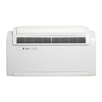
2.4.7 - TOP/BOTTOM INSTALLATION CONFIGURATION
Thisunitmaybeinstalledeitherasalowwallapplication(adjacenttotheoor)orhighwallapplication(ad-
jacent to the ceiling). The air stream can be adjusted to optimize air distribution and occupant comfort by
changing the position of the supply air fap.
Figure31referstoaunitconguredforalowwallapplication,wheretheairowsupwards.Thesamecongu-
rationmayalsobeusedtoinstalltheunitinahighwallapplication,allowingforincreasedairowinthespace.
Figure32referstoaunitconguredforahighwallapplication,wheretheairowsdownwards.
THE FOLLOWING OPERATIONS MUST BE PERFORMED WHEN THE UNIT IS SWITCHED OFF AND
DEENERGIZED.
Changingtheconguration(seeg.31-32):
a. Carefullyopenthesupplyairap.
b. Unhooktheap(sideandcentralhooksfromthebafes).
c. Remove the pin (P1) and turn the fap 180°.
d. Insert the pin (P1) on the right-hand side of the fap.
e. Insert the fap into the unit by inserting the pin into the top hole on the right-hand side in the opening (P2),
andtheap’sleft-handholeontheupperpinthatisontheleft-handsideintheopening.
Afterhavingperformedthestepsrequiredtochangethesupplyairapposition,itisnecessarytocongure
the unit’s control board by following the instructions listed in section 2.5 of this manual.
FOR PROPER UNIT OPERATION EACH TIME THE CONFIGURATION OF THE SUPPLY AIR FLAP
IS MODIFIED THERE MUST BE A CORRESPONDING CHANGE TO THE UNIT CONTROL BOARD
SETTINGS.
Prior to starting the unit the two additional lters (1 green purifying lter and 1 black active carbon
lter) included in the parts bag that comes supplied with the unit, must be installed. Refer to section
2.6.1, which describes how to clean the lters, as well as how to remove and reinstall them.
2.5 - OPERATING TESTS AND TROUBLESHOOTING (Fig.B)
The unit is able to perform a brief troubleshooting cycle to check that the internal components are operating
normally.Duringthisprocesstheinstallercancongurethecontrolboardbasedonwhetherinstallationis
a low wall or high wall application.
To activate the troubleshooting function, use the following procedure:
• Turnontheunitandensureitisonstand-bymode(noLEDshouldbeilluminatedontheconsole).
• Presstheresetbuttonpositionedunderneaththeholetotheleftsideoftheconsole(H),withapointed
object for at least 10 seconds. The beeping sound indicates the troubleshooting function has been ac-
tivated.