Do you have a question about the Olimpia splendid MAESTRO SMART 9HP and is the answer not in the manual?
Indicates actions that could cause injury or death.
Indicates actions that could cause malfunction or damage.
Highlights important information and delicate steps.
Read manual, ensure correct installation, follow procedures.
Proper grounding, no adapters/extension cords, correct outlet.
Follow safety procedures, use protective equipment for refrigerant.
Caution with torches, use fireproof materials, keep extinguisher.
Do not operate with grilles removed, keep hands away from fan.
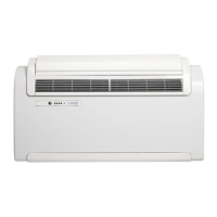
Identifies main physical components of the unit.
Details performance data, power, dimensions, and operating limits.
Provides physical measurements and diagrams of the unit.
Explains the buttons and indicators on the unit's control panel.
Details buttons and display symbols for unit operation.
Unit manages mode and fan speed based on temperature.
Unit dehumidifies and cools; compressor/fan operation explained.
Operation for heat pump units; temperature settings and fan control.
Explains when and how the defrost cycle is activated.
Unit operates in dehumidify-only mode; compressor control logic.
Unit operates with fan only; alarms/notices enabled.
Adjusts settings for comfortable sleep; fan speed and temperature changes.
Unit behavior after power interruption; standby or prior mode resume.
Unit state when idle; restoring settings upon restart.
Selecting fixed or automatic oscillation for the air deflector.
Setting start and stop times for unit operation.
Procedures for air conditioner and board auto tests.
Procedures for handling condensate water.
Illustrates the electrical connections and components of the unit.
Details voltage and frequency requirements for the unit.
Illustrates the refrigerant flow during cooling operation.
Illustrates the refrigerant flow during heating operation.
Lists all parts provided for unit installation.
Recommendations for optimal placement for ceiling/floor install.
Procedures for drilling, draining, and connecting components.
Details on installing air intake and external grilles.
Steps for physically mounting the unit.
Instructions for safely connecting the unit to power.
Steps to turn the unit on for the first time.
Table of alarm codes and their indicator light status.
Indicates when the air filter needs cleaning or replacement.
Alarms related to internal/external sensor faults or ranges.
Alerts for high temperatures in internal or external heat exchangers.
Triggered when heat exchanger temperature falls too low.
Alerts for issues with condensate water level or pump.
Detects incorrect operation of the condensate pump.
Indicates invalid or lost data in the unit's memory.
Alarm triggered by internal fan speed issues.
Alerts for condenser assembly temperature issues.
Triggered by excessive external coil temperature.
Triggered by excessive internal coil temperature.
Details the 4-way valve component.
Shows the arrangement of components on the power board.
Describes the unit's display interface.
Details the thermoactuator and shutoff valve components.
Information on the ambient temperature sensor.
Details the external temperature sensor.
Information on the evaporator sensor.
Details the condenser sensor.
Explains the level sensor component.
Information on the unit's pump.
Details the internal tangential fan.
Information on the external fan.
Details the compressor unit.
Information on the evaporator assembly.
Details the condenser assembly.
Information on the louver motor.
Details the condensate slinger assembly.
Information on the unit's capacitors.
Warnings regarding electrocution, pressure, burns, freezing, explosion.
Step-by-step guide to remove and clean the air filter.
Instructions for removing the unit's body panels.
Guide to removing the front panel.
Instructions for accessing the electronic board housing.
Steps to remove the unit's grilles.
Guide to removing the back panel of the unit.
Instructions for removing the external fan.
Steps to remove the upper tank assembly.
Guide to removing the internal fan.
Instructions for removing the display board.
Steps to remove the main electronic assembly housing.
Guide to removing the main control board.
Instructions for removing the unit's capacitors.
Steps to remove the pump, sensors, and valve assembly.
Guide to removing the cabling cover.
Instructions for removing the thermoactuator assembly.
Steps to remove the condensate pump.
Guide to removing the intermediate tank assembly.
Instructions for removing the condenser slinger assembly.
Procedures for handling refrigerant gas.
Steps to remove the condenser assembly.
Guide to removing the evaporator assembly.
Instructions for removing the compressor.
Steps to remove the unit's floats.
Introduction to the Wi-Fi kit for remote control.
Details the Wi-Fi board layout and technical data.
Steps for installing the Wi-Fi kit and connecting cables.
Guide to downloading, installing, and setting up the app.
Instructions for periodic cleaning or replacement of the air filter.
Procedures for preparing the unit for extended periods of non-use.
How to maintain the condensate water drain system.
Guide for cleaning the exterior of the climate control unit.
Table outlining recommended maintenance tasks and frequency.
Provides resistance values for sensors at different temperatures.
| Model | MAESTRO SMART 9 HP |
|---|---|
| Type | Heat Pump |
| Wi-Fi | Yes |
| Dimensions (Outdoor Unit) | N/A - Monobloc System |
| Cooling Power | 9 kW |
| Heating power | 10 kW |
| Timer | Yes |