2
SYMBOLS USED IN THIS MANUAL AND THEIR
MEANING
To identify actions that, if not performed correctly, may cause
general accidents, personal injury, or death.
To identify actions that, if not performed correctly, may cause general
accidents, or may cause malfunctions.
To identify important information and particularly delicate steps.
An identification label is on the unit, showing the device information.
TABL
E OF CONTENTS
1 WARNINGS AND SAFETY RULES 4
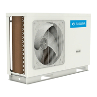
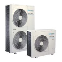
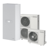
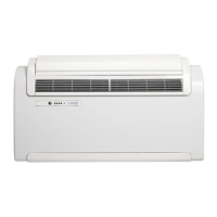
2 DESCRIPTION OF UNIT 5
2.1 Structure ........................................................................... 5
2.2 Technical features ............................................................ 6
2.3 Dimensions ...................................................................... 7
2.4 Control panel .................................................................... 8
2.4.1 Operating conditions ............
......
................. 8
2.5 Remote control ................................................................. 8
2.5.1 Buttons ...........................
......
....................... 8
2.5.2 Display ........................................................ 9
3 OPERATING LOGIC 10
3.1 Automatic mode ............................................................. 10
3.2 Cooling mode ................................................................. 10
3.3 Heating mode (only for heat pump units) ....................... 11
3.4 Defrosting ....................................................................... 11
3.5 Dehumidifier only mode ................................................. 12
3.6 Fan only mode ............................................................... 12
3.7 Nighttime comfort mode ................................................. 12
3.8 Auto restart function ....................................................... 12
3.9 Standby mode ................................................................ 12
3.9.1 Air outlet
louver
control
.............................
13
3.10 Timer programming ........................................................ 13
3.11 Air conditioner auto test mode ....................................... 13
3.12 Board auto test mode ..................................................... 14
3.13 Condensate draining and disposal ................................. 14
4 ELECTRICAL DIAGRAM 15
5 COOLING CIRCUIT 16
5.1 Cooling circuit with 4-way valve diagram ....................... 16
5.2 Heating circuit with 4-way valve diagram ....................... 16
6 INSTALLATION 17
6.1 Included items ................................................................ 17
6.2 Position .......................................................................... 17
6.2.1 Installation at ceiling level ......................... 17
6.2.2 Installation at floor level ............................ 17
6.3 Assembly ........................................................................ 18
6.3.1 Drilling into the wall ................................... 18
6.3.2 Draining condensate ................................. 18
6.3.3 Condensate drain connection to the unit .. 18
6.3.4 Air intake ................................................... 19
6.3.5 External grille ............................................ 19
6.3.6 Location of holes on the unit ..................... 19
6.4 Mounting the unit ............................................................ 20
6.5 Electrical connections .................................................... 20
6.6 Turning the unit ON ........................................................ 20
 Loading...