24/02/2020 17 / 24 923650001_09_008.doc
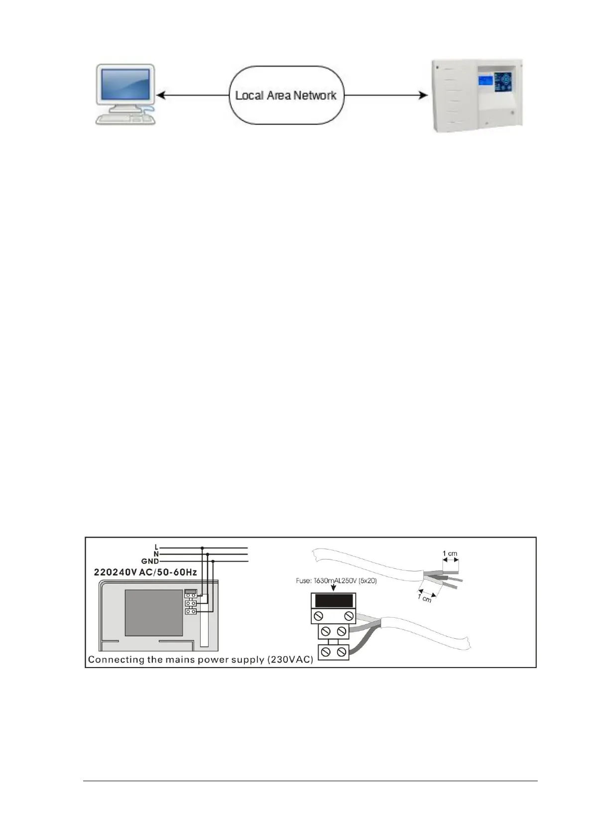
Set the IP (IPv4) Address of the panel before connecting it to the Local Area Network, via
TECHNICIAN MENU > NETWORK > IP ADDRESS. Then you can access the panel for monitoring
and control, via a common web browser (see chapter 5. for more info).
3.7. Relay operation
The panel has 3 relay contacts to connect them to a BMS. Each relay has been programmed
for a certain operation, described below:
• Relay 1: Activated when the panel is active/working.
• Relay 2: Activated when the panel is in emergency mode.
• Relay 3: Activated when there are not any faults in the panel.
3.8. USB connection
At the right bottom corner of the panel PCB there is a mini USB-B connector. This USB is
used for communication between the panel and the software PC GR-6500. You can update the
firmware of the panel by using the software too.
3.9. Other connections
Connecting the battery and the mains power supply:
For the battery there are two cables, red and black for connecting to the positive and negative pole
respectively.
Finally there are two outputs 24VP and OUT. The 24VP is an output 24 VDC. The OUT gives 24VDC
when the panel is in test mode.