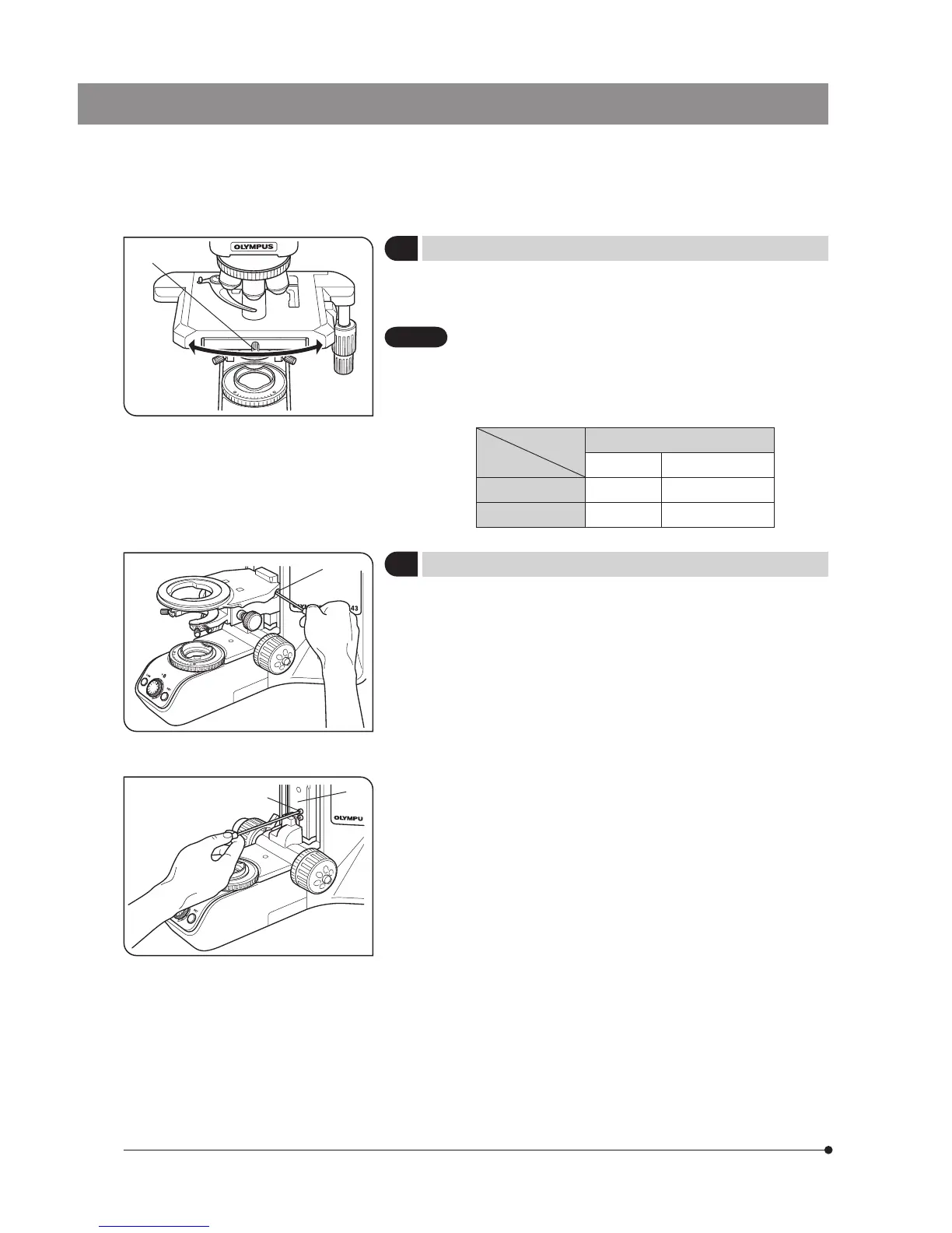
4 Rotating the Stage
(Fig. 28)
1. Slightly loosen the stage clamping screw @.
2. The stage can be rotated both clockwise and counterclockwise by the
stage clamping screw.
A click may be heard and felt during rotation. However, this is
due to the construction of the substage and does not indicate
a malfunction.
} The angle of rotation varies depending on the positions of the X- and
Y-axis knobs.
Angle of Rotation
Clockwise Counterclockwise
Right hand knobs
230° 20°
Left hand knobs 20° 230°
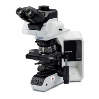
5 Adjusting the Stage Height
(Figs. 29 & 30)
} By lowering the position of the substage, the microscope will accommo-
date specimens with maximum height of 35 mm. This is useful when
observing metallurgical specimens and other thick objects.
1. Lower the stage to the lower limit, then remove the stage from the
microscope.
2. Using the Allen screwdriver, loosen the substage bracket clamping screw
@ and remove the substage.
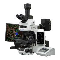
3. Turn the coarse adjustment knob and raise the focusing block 3 to where
the stopper screw 2 on the arm becomes visible.
4. Using the Allen screwdriver, loosen and remove the upper stopper screw
2.
5. Reattach substage bracket and stage.
} Store the removed stopper screw 2 in a safe place so that it will not be
lost, if needed again.
Fig. 28
Fig. 29
Fig. 30
1
1
2
3
CAUTION