2
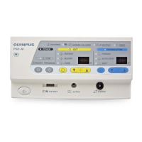
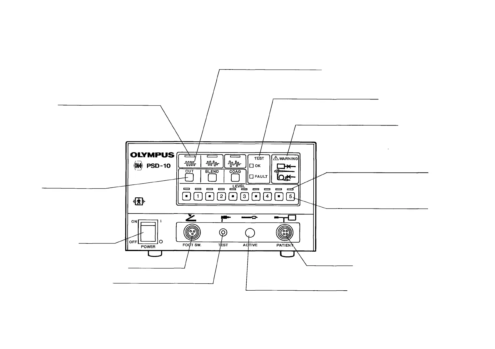
DESCRIPTION OF CONTROLS
Selected Current Indicators
Light when the switch under the indicator
is pressed.
Output Indicators
Light to indicate the selected current
(CUT, BLEND or COAG) is being delivered
when the footswitch is depressed.
Current Selector Switches
Output Test Indicators
Indicate normal or abnormal test con-
ditions.
Defective Connection Indicators
Light to indicate defective connection of
cords or broken wire in S-P cord.
Output Level Indicators
Light when the switch under the indicator
is pressed.
Output Adjustment Switches
Output level from 0.5 to 5.0 (with 0.5
increment) is selected.
Power Switch
Footswitch Connector
TEST Connector
Accepts the smaller plug of Check Lead
(for test).
Patient-plate
Connector
Accepts S-P cord.
Active Cord Connector
Accepts A-cord (for electrosurgery) or the
larger (clip-tipped) plug of Check Lead
(for test).