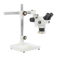
The Olympus SZX2-ILLC16/ILLC10 is a coaxial vertical illuminator designed for use with Olympus SZX16, SZX10, and SZX7 stereo microscopes. This instruction manual provides comprehensive guidance for its safe use, assembly, operation, and maintenance, ensuring optimal performance and user familiarity.
Function Description:
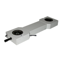
The SZX2-ILLC16/ILLC10 coaxial vertical illuminator provides incident illumination for observing specimens, particularly those with mirror-type or scattering surfaces. Coaxial illumination means that the light travels along the same optical path as the observation light, resulting in bright, shadow-free illumination that is ideal for inspecting highly reflective surfaces like IC chips, wafers, and liquid crystals. When used with a quarter-wave plate (SZX2-ILLC1/4), it also enables reflected light polarized observation, which is crucial for analyzing birefringent materials and revealing structural details not visible under standard brightfield illumination. The illuminator integrates with the microscope body and a branched flexible light guide (LG-DF) connected to a light source unit (e.g., LG-PS2) to deliver controlled and adjustable illumination.
Important Technical Specifications:
- Compatibility: Designed for Olympus SZX16, SZX10, and SZX7 stereo microscopes.
- Illumination Type: Coaxial vertical illumination.
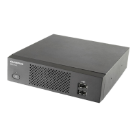
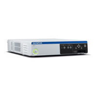
- Light Guide: Utilizes a branched flexible light guide (LG-DF) for light delivery from an external light source unit (e.g., LG-PS2).
- Quarter-Wave Plate: Compatible with the SZX2-ILLC1/4 quarter-wave plate for polarized observation.
- Magnification: The total magnification when using the coaxial vertical illuminator is calculated as: Objective magnification × Zoom magnification × Eyepiece magnification (10X) × 1.5.
- SZX2-ILLC16 (with SZX2-ZB16 Zoom Microscope Body):
- SDFPLFL0.3X: Total Mag. 18X, Zoom Mag. 4X
- SDFPLAPO0.5XPF: Total Mag. 19X, Zoom Mag. 2.5X
- SDFLPLAPO0.8X: Total Mag. 12X, Zoom Mag. 1X
- SDFPLAPO1XPF: Total Mag. 37.5X, Zoom Mag. 2.5X
- SDFPLAPO1.6XPF: (Data not provided in table)
- SDFPLAPO2XPFC: (Data not provided in table)
- ILLC10 (with SZX2-ZB19 Zoom Microscope Body):
- DFPL0.5X-4: Total Mag. 15X, Zoom Mag. 2X
- DFPL0.75X-4: Total Mag. 14X, Zoom Mag. 1.25X
- DFPLAPO1X-4: Total Mag. 12X, Zoom Mag. 0.8X
- SZX-ACH1X: Total Mag. 15X, Zoom Mag. 1X
- DFPLAPO1.25X: Total Mag. 12X, Zoom Mag. 0.63X
- SZX-ACH1.25X: Total Mag. 12X, Zoom Mag. 0.63X
- DFPL1.5X-4: Total Mag. 56X, Zoom Mag. 2.5X
- DFPL2X-4: Total Mag. 96X, Zoom Mag. 3.2X
- ILLC10 (with SZX-ZB7 Zoom Microscope Body):
- DFPL0.5X-4: Total Mag. 19X, Zoom Mag. 2.5X
- DFPL0.75X-4: Total Mag. 18X, Zoom Mag. 1.6X
- DFPLAPO1X-4: Total Mag. 15X, Zoom Mag. 1X
- SZX-ACH1X: Total Mag. 19X, Zoom Mag. 1.25X
- DFPLAPO1.25X: Total Mag. 15X, Zoom Mag. 0.8X
- SZX-ACH1.25X: Total Mag. 15X, Zoom Mag. 0.8X
- DFPL1.5X-4: Total Mag. 18X, Zoom Mag. 0.8X
- DFPL2X-4: Total Mag. 60X, Zoom Mag. 2X
- Light Guide Bending Radius: Minimum 60 mm to prevent damage and light loss.
Usage Features:
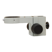
- Assembly:
- The coaxial vertical illuminator mounts directly above the zoom microscope body, with the observation tube placed on top of the illuminator.
- The branched flexible light guide (LG-DF) connects the light source unit (e.g., LG-PS2) to the illuminator. The incident light guide end inserts into the light source unit, and the outgoing light guide end inserts into the illuminator. Both connections are secured with clamping screws/knobs.
- The SZX2-ILLC1/4 quarter-wave plate attaches to the tip of the objective lens, secured by clamping knobs. It should be oriented so that the clamping knobs are on the side when viewed from the front of the microscope (module indication facing front).
- Operation Procedure:
- Preparation: Ensure all modules are correctly mounted. Adjust microscope body orientation and coarse focus knob tension. Turn on the light source unit and adjust brightness.
- Quarter-Wave Plate Adjustment: For optimal observation and to prevent flare, the quarter-wave plate's orientation must be adjusted. Slightly loosen its clamping knobs and rotate the plate until the clamping knobs are exactly to the side of the microscope (module indication facing front).
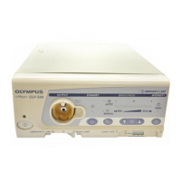
- Brightness Adjustment: Brightness can be adjusted by turning the light intensity adjustment knob on the light source unit or by adjusting the iris aperture lever on the light source unit. Note that adjusting bulb voltage also changes the color temperature.
- Observation:
- For IC chips, wafers, etc. (brightfield coaxial observation): Brighten the field of view by turning the quarter-wave plate rotation annulus. If the view is too bright, adjust the brightness using the light source unit controls.
- For liquid crystal (reflected light polarized observation): Perform Cross-Nicol observation by rotating the quarter-wave plate rotation annulus to achieve the darkest possible field of view. For accurate adjustment, use a flat, mirror-surfaced specimen. Observe the specimen by rotating it on a horizontal plane.
- Safety Precautions:
- Handle the illuminator as a precision instrument, avoiding sudden impacts.
- Ensure the light guide bending radius is 60 mm or more to prevent damage.
- Avoid direct sunlight, high temperatures, humidity, dust, and vibrations.
- Always use the equipment as outlined in the manual to prevent bodily harm or equipment damage.
Maintenance Features:
- Cleaning Lenses and Glass Components:
- Use a commercially available blower to remove dust.
- Gently wipe with cleaning paper or clean gauze.
- For fingerprints or oil smudges, use gauze slightly moistened with commercially available absolute alcohol.
- Caution: Absolute alcohol is highly flammable. Handle with care, keep away from open flames or electrical sparks, and use in a well-ventilated room.
- Cleaning Non-Optical Components:
- Do not use organic solvents.
- For stubborn smudges, wipe with a soft cloth slightly moistened with a diluted neutral detergent.
- Disassembly: Never disassemble any part of the unit, as this can cause malfunctions or reduced performance.
- Storage: Retain the instruction manual in an easily accessible place for future reference.
Troubleshooting Guide:
- Field of view not evenly illuminated:
- Cause: Light guide not mounted properly or bulb of light source unit not mounted properly.
- Remedy: Mount the light guide and/or bulb properly.
- Poor color reproduction in photography:
- Cause: Brightness control of power transformer not set to maximum position, or filters (30.5S-LB80 and 30.5-LBD) not used with daylight type film.
- Remedy: Set brightness control to maximum position and/or mount appropriate filters on the LG-PS2 light source unit.
- Poor contrast:
- Cause: Quarter-wave plate not adjusted.
- Remedy: Adjust the quarter-wave plate orientation (refer to Page 9).
- View noticeably different between left and right fields of view:
- Cause: Quarter-wave plate clamping position not adjusted properly.
- Remedy: Adjust the quarter-wave plate clamping position correctly (refer to Page 9).
If problems persist after checking the troubleshooting guide, contact your local Olympus representative.