O.M.A.C. s.r.l.
Via Giovanni Falcone, 8 42048 Rubiera (RE) - Italy Tel.0522/629371 - 629923 Fax 0522/628980
Rev.4 del 01/2011 O.M.A.C. s.r.l.
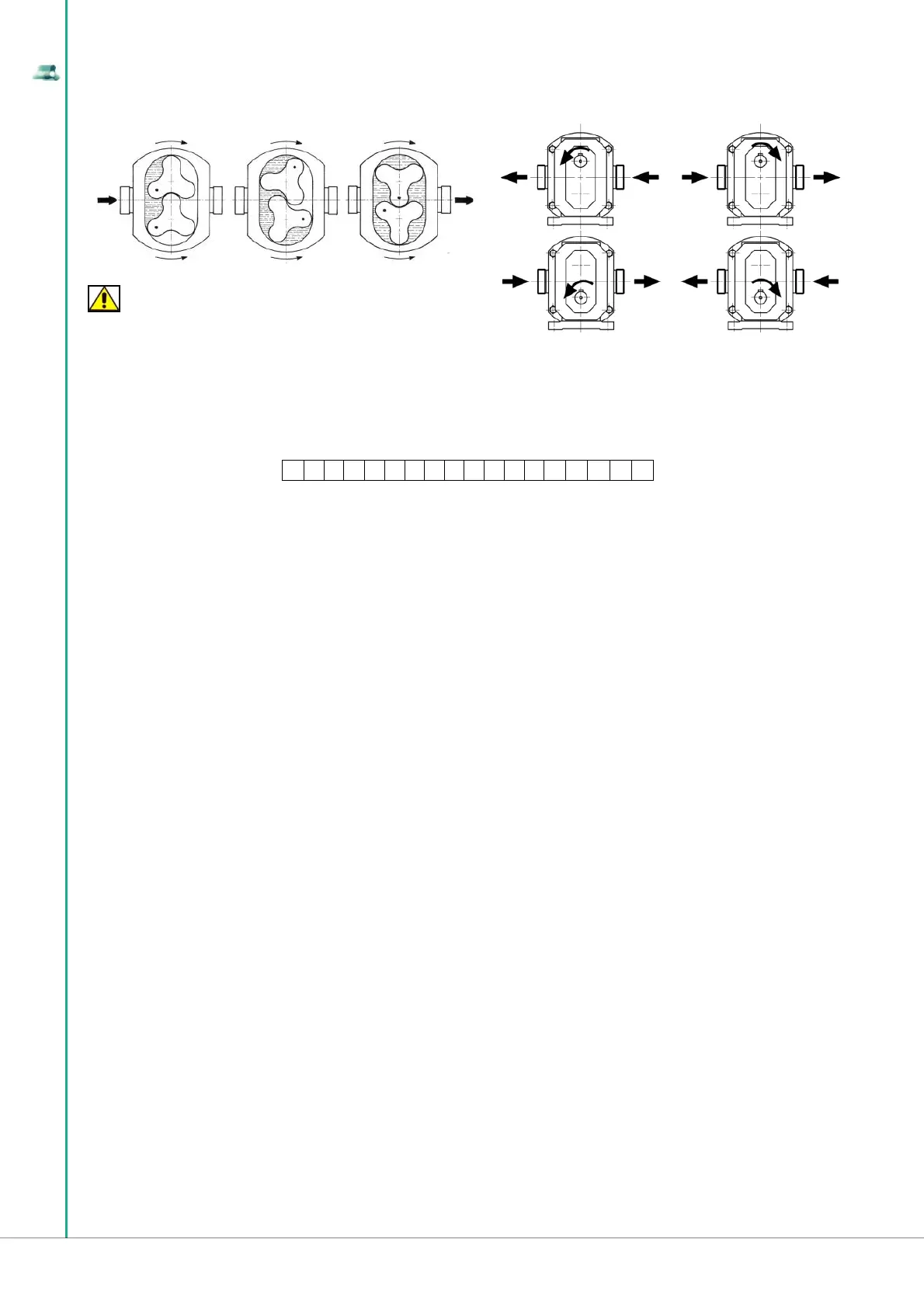
FRONTAL VIEW OF THE PUMP CHAMBER REAR VIEW OF THE PUMP SHAFT
WARNING
If the control unit does not comply with the rotation direction indicated in the fi gure,
the mechanical functionality of the LDPU is not compromised, but will not supply any delivery capacity.
Failure to comply with the proper connection to the unit (suction inlet connected to the suction piping and delivery outlet connected to the unit delivery
pipe) will cause improper installation of the LDPU by the customer.
1.2.2 B Series lobe positive diplacement pump coding
The LDPU is identifi ed by an item code, represented by a string of 18 alphanumeric characters that starts with “K” (the item code is detectable on the fi rst
line of the technical sheet of which there is an example in section 1.3) divided into the following structure:
Fields 1-1: pump series = “BO”
Field 2: pump size
A = 100; B = 105; C = 110; D = 115; E = 215; F = 220; G = 325; H = 330; L = 390; M = 430; N = 440; P = 470; Q = 490;
R = 550; T = 660; U = 680;
Field 3: seal type
0 = UM type - S1 type - HN Elring type;
1 = Tefl on packing;
2 = Tefl on packing + liquid barrier;
3 = Single Mechanical Stainless Steel/Carbon;
4 = Single Mechanical Tungsten carbid/Carbon;
5 = Single Mechanical Tungsten carbid/Tungsten carbid;
6 = Single Mechanical Ceramic/Carbon;
7 = Single Mechanical Ceramic/Rulon;
8 = Single Mechanical Silicon carbid/Silicon carbid;
9 = Single Mechanical Tungsten carbid/Silicon carbid;
Field 4: suction-discharge connections type
0 = GAS-BSP;
1 = fl anged PN16 UNI EN 1092-1 – DIN2576;
2 = DIN 11851;
3 = SMS;
4 = RJT (BS);
5 = IDF-ISS;
6 = TRI-CLAMP;
7 = GAS;
8 = wine fi tting;
Field 5: tipo di rotori:
(ST= standard rotor clearance; SM = increased rotor clearance; PR = exact rotor clearance)
A = Single Mechanical Silicon carbid/Carbon;
B = Opened frontal lip;
C = Frontal o-ring;
D = Closed frontal lip;
M = Double lip 2HN in PTFE;
N = Single lip HN in PTFE;
P = Frontal lip in PTFE;
Q = Single lip HN modifi ed (heat-welded);
R = Double lip 2HN modifi ed (heat-welded);
A = Aseptic O.M.A.C.;
B = DIN 11864/1a;
C = DIN 11864/2a;
D = DIN 11864/3a;
E = DIN 11864/1b;
F = DIN 11864/2b;
G = DIN 11864/3b;
H = fl anged PN40 UNI 6084-67/DIN 2501;
J = fl anged ASME 150lb;
K = fl anged IDF;
L = smooth for welding;
M = DS 722;
N = DIN 11851 (male);
P = MACON;
Q = fl anged 5044/DIN 11850;
R = ISO KF CLAMP;
0 = Trilobe
1 = Trilobe/Gear
2 = Bilobe
3 = Bilobe
4 = Trilobe
5 = Dual Wing
6 = Bilobe
7 = Trilobe/Gear
8 = Gear
9 = Quadrilobe
A = Bilobo
Stainless Steel
Stainless Steel
Stainless Steel
Stainless Steel
Stainless Steel
CY5SnBIM(antiseizure)
Stainless Steel
CY5SnBIM (antiseizure)
Stainless Steel
Stainless Steel
CY5SnBIM(antiseizure)
ST;
SM;
ST;
SM;
ST;
ST;
ST;
ST;
ST;
ST;
ST;
B = Dual Wing
C = Dual Wing
E = Quadrilobe
F = Trilobe
L = Trilobe/Gear
M = Dual Wing
N = Trilobe
P = Dual Wing
Q = Gear
R = Gear
Stainless Steel
Stainless Steel
Stainless Steel
Stainless Steel
CY5SnBIM (antiseizure)
CY5SnBIM (antiseizure)
CY5SnBIM (antiseizure)
CY5SnBIM (antiseizure)
CY5SnBIM (antiseizure)
CY5SnBIM (antiseizure)
ST
SM
SM
SM;
SM;
SM;
PR;
PR;
ST ultrareducted;
ST reducted;
K 1 1 2 3 4 5 6 7 7 7 8 8 9 V V V V