O.M.A.C. s.r.l.
Via Giovanni Falcone, 8 42048 Rubiera (RE) - Italy Tel.0522/629371 - 629923 Fax 0522/628980
Rev.4 del 01/2011 O.M.A.C. s.r.l.
1.3.3 Motorization and transmission coupling technical features
The mechanical features of the fl exible transmission coupling and the performance features of the control unit (electrical, pneumatic, hydraulic), accor-
ding to the type of operation chosen by the customer, are shown in the respective use and maintenance manuals; documents that are supplied with the
LDPU.
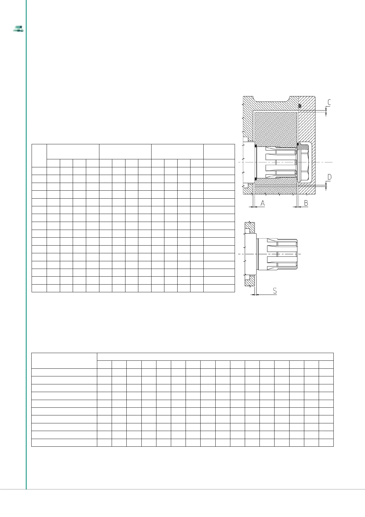
1.3.4 Rotors clearances
1.3.5 Rotors geometry
The table below shows the types of rotors, per type of construction material and geometric shape, available for every size of “B series lobe pump”.
ROTOR TYPE
B SERIES MODEL PUMP
B100 B105 B110 B115 B215 B220 B325 B330 B390 B430 B440 B470 B490 B550 B660 B680
GEAR S.S. AISI 316 L ● ●
GEAR CY5SnBIM ● ●
DUAL-WING S.S. AISI 316 L ●
DUAL-WING CY5SnBIM ● ● ● ● ● ● ● ● ● ● ● ● ● ● ●
TRILOBE S.S.AISI 316 L ● ● ● ● ● ● ● ● ● ● ● ● ● ●
TRILOBE CY5SnBIM ● ● ● ● ● ● ● ●
RUBBER COATED TRILOBE (*) ● ● ● ● ● ● ● ●
BILOBE S.S.AISI 316 L ● ● ● ● ● ● ● ● ● ● ● ● ●
BILOBE CY5SnBIM ● ● ● ● ● ● ● ● ●
RUBBER COATED BILOBE ● ● ● ● ●
(*) Penta-lobe for B100 and B105
ROTORS S.S. AISI 316 L
ST VERSION
ROTORS S.S. AISI 316 L
SM VERSION
ROTORS ANTISEIZURE
CY5SnBIM
SHAFT
PROTRUSION
A B C D A B C D A B C D S
B100 0.12 0.12 0.15 0.2 0.15 0.15 0.2 0.2 0.07 0.08 0.19 0.15 0.12
B105 0.12 0.14 0.15 0.25 0.17 0.19 0.2 0.3 0.05 0.05 0.13 0.15 0.12
B110 0.14 0.14 0.15 0.3 0.19 0.19 0.23 0.3 0.08 0.07 0.15 0.2 0.14
B115 0.14 0.14 0.18 0.3 0.19 0.19 0.22 0.3 0.07 0.08 0.2 0.2 0.14
B215 0.15 0.15 0.18 0.3 0.22 0.23 0.3 0.3 0.08 0.07 0.18 0.2 0.15
B220 0.15 0.17 0.23 0.3 0.25 0.25 0.32 0.3 0.08 0.07 0.2 0.2 0.15
B325 0.17 0.17 0.2 0.35 0.25 0.25 0.32 0.35 0.08 0.08 0.2 0.2 0.17
B330 0.17 0.19 0.23 0.35 0.27 0.28 0.32 0.35 0.09 0.08 0.23 0.2 0.17
B390 0.17 0.19 0.23 0.35 0.27 0.28 0.32 0.35 0.09 0.08 0.23 0.2 0.17
B430 0.18 0.18 0.22 0.35 0.27 0.27 0.32 0.35 0.09 0.08 0.23 0.2 0.18
B440 0.18 0.18 0.22 0.35 0.27 0.27 0.32 0.35 0.1 0.1 0.25 0.2 0.18
B470 0.2 0.2 0.27 0.35 0.32 0.32 0.35 0.35 0.09 0.09 0.25 0.2 0.2
B490 0.23 0.23 0.3 0.35 0.35 0.35 0.35 0.45 0.09 0.09 0.25 0.2 0.23
B550 0.22 0.22 0.3 0.4 0.32 0.32 0.43 0.4 0.15 0.15 0.35 0.25 0.22
B660 0.27 0.27 0.35 0.5 0.37 0.37 0.5 0.5 - - - - 0.27
B680 0.3 0.35 0.35 0.5 0.37 0.37 0.5 0.5 - - - - 0.27
Dimensions expressed in mm - Tolerances 0/+0.03
This section lists the nominal clearances (ST standard, SM increased), that are recorded between rotors
and walls of the pumping chamber according to the material (AISI 316 L, anti-friction alloy CY5SnBIM).
The fi gure, on the next page, represents a rotor section, fi tted in the pumping chamber, with indication
of clearances, identifi ed by letters A,B,C,D. The table below shows the entity of these clearances.
The “S” value represents the protrusion of the shaft compared to the wall of the pumping chamber.