9
O.M.A.C. s.r.l.
Via Giovanni Falcone, 8 42048 Rubiera (RE) - Italy Tel.0522/629371 - 629923 Fax 0522/628980
E-mail:info@omacpompe.com SitoWeb:www.omacpompe.com
Rev.4 del 01/2011 O.M.A.C. s.r.l.
Chap.5 - pag.
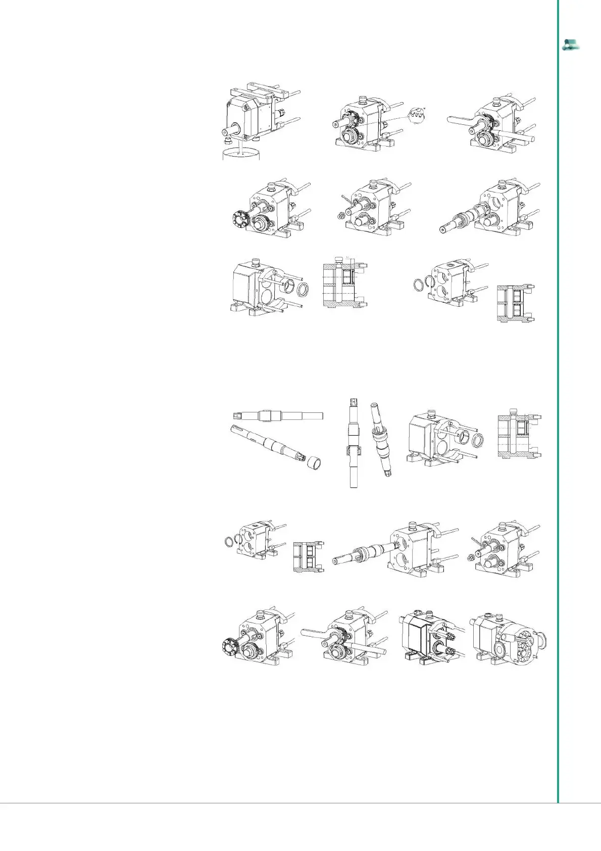
5.7.3 DISASSEMBLY OF THE BEARINGS BOX
5.7.4 Assembly of the bearing box
15 After disassembling the rotor case, drain the
oil and the remove drive key on shaft
16 Remove the gear cover and make a refe-
rence mark on gears in order to respect the right
timing while reassembling
17 Disconnect the retainer keys on lock
washers
18 Unscrew the gear ring nut, inserting a non
metal wedge between gears in order to stop
turning
19 Disassemble the shafts, unscrewing the fl
athead screw, with the lock washer
20 Extract the shafts by the posterior side of
the pump
21 extract the oil retainer and the external rings
of the front bearing
22 extraxt the spacers and the snap rings
23 *BEARING ASSEMBLING PHASE*
Prepare the shafts and the bearings, checking
they are without dents and burrs
24 Drive the inner ring on the driving shaft. Re-
peat the operation on the drived shaft
25 Assemble the rear bearing on the driving
shaft and then on the drived one
26 Drive the external bearing rings on the gear
box, observing the depth on the fi gure (10 mm)
27 Insert the snap rings and the spacers for
the axial setting
28 Assemble the shafts by the rear side of the
pump, respecting the timing previously marked
while reassembling, with the numbers marked
“1” and “2” turned towards the high
30 The gear couple is composed by a fi xed gear and an adjustable one. Assemble the fi xed gear, then the adjustable one with untightened screws,
taking care to a fi rst approximate rotor timing
29 Fixed the rear bearings with the washers
and the fl athead screws
31 Tighten the retainer ring nuts with the corresponding safety washers and set rightly the suited retainer key. In order to avoid turning during operation
insert a wedge in soft material among the gear teeth
33 Being the wedge inserted among the gears tighten the rotor nuts, taking care of the driving torque (see par.1.3.6)
32 Assemble the rotor case and rotors as previously described and check the “Clearences” (see par.1.3.4).
If rotor clearances are not included in tolerances as prescribed in chap. 1, disassemble rotors, the rotor case and adjust the spacer according to the
requested dimension
15
16 17
18
19
20
21
22
23+24 25 26
27 28 29
30 31 32 33