1
O.M.A.C. s.r.l.
Via Giovanni Falcone, 8 42048 Rubiera (RE) - Italy Tel.0522/629371 - 629923 Fax 0522/628980
E-mail:info@omacpompe.com SitoWeb:www.omacpompe.com
Rev.4 del 01/2011 O.M.A.C. s.r.l.
Chap.1 - pag.
CHAPTER 1: MACHINE AND PUMPED FLUID SPECIFICATIONS
1.1 Envisioned duration
Given the quality level of the materials and construction technologies used, if you strictly follow the instructions in this OMM (paying particular attention
to chapters 3, 4 and 5, relating, respectively, to the installation, use and maintenance of the LDPU), the expected duration of such subject matter is
estimated to be 12 months from date of installation.
Please note that, during its expected life-span, the LDPU must not be assembled and/or disassembled by unauthorised personnel and furthermore the
instructions contained in this UMM must be followed scrupulously.
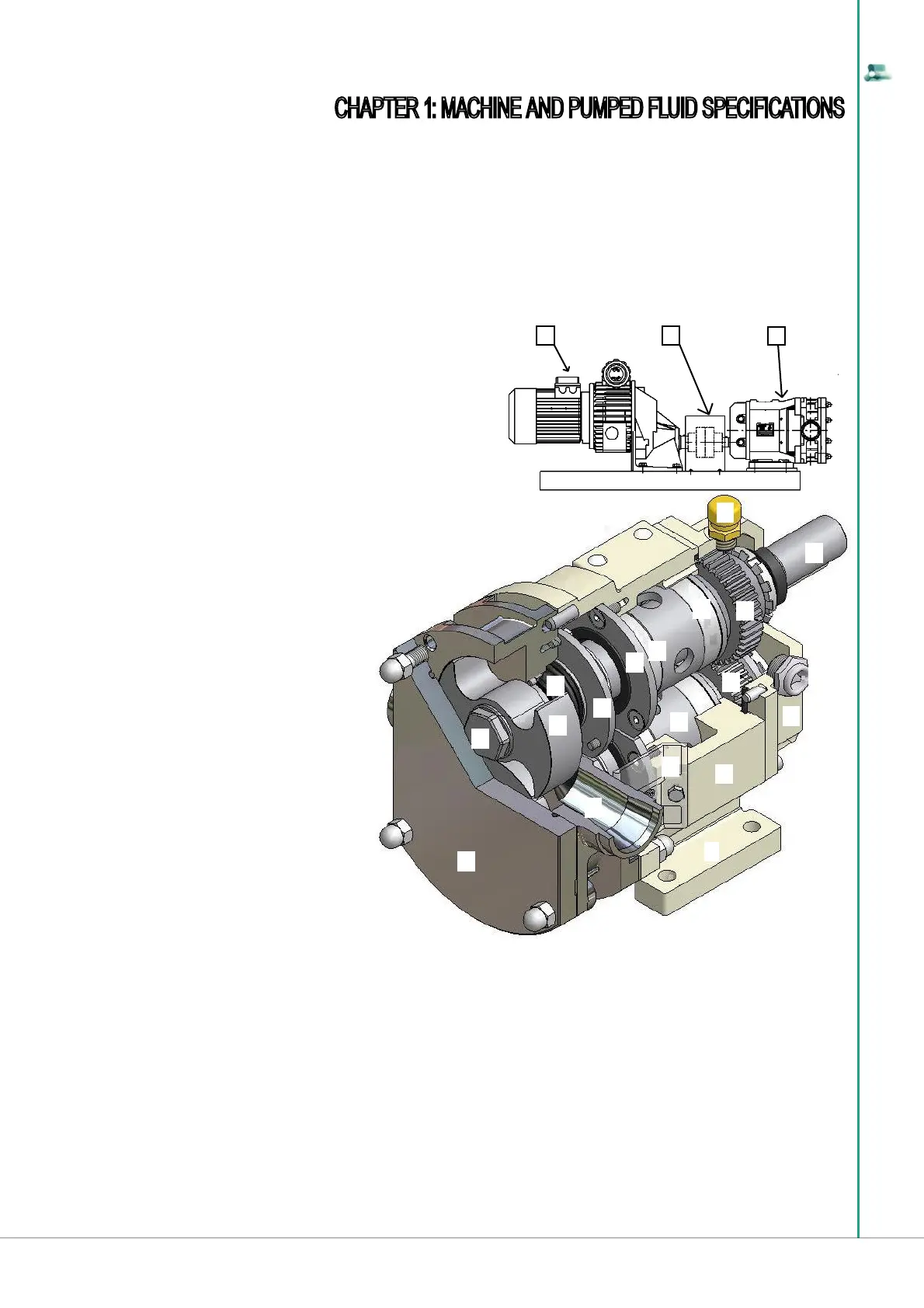
1.2 Technical description of the machine
Below there is a brief description of the LDPU, as well as a functional illustrational of the B series LDPU, in order to more easily identify the main con-
struction details, mentioned in the description of use and maintenance of this document.
The LDPU is made up of 3 macro-components:
1) control unit (gear motor, speed controller, hydraulic motor,
electric panel, etc.);
2) mechanical transmission device (fl exible transmission coupling);
3) B Series LDPU;
The B Series LDPU, identifi ed with number 3)
is made up as follows:
A = Rotorcase cover
B = Lock nut
C = Rotor
D = Seal
E = Balancing ring
F = Bearing retainer ring
G = Front Bearing
H = Rear bearing
K = Oil vent cap
L = Rear cover
1.2.1 Operation principle of the B Series
LDPU.
The LDPU is reversible: full performance can be achieved in both rotation directions of the pump rotors (section 1.3.5 of chapter 1 lists the types of rotors
used).
The pumping action of the B series lobe displacement pump is achieved thanks to the counter-rotation of two rotors (letter “C” indicated in the fi gure in
section 1.2, indicating one of the two rotors), housed inside the pumping chamber (letter “U” indicated in the fi gure in section 1.2 or see fi gure below). The
rotors are assembled on rotating shafts supported by bearings (letters “G” and “H” shown in the fi gure in section 1.2), which are housed in the external
gearbox (letter “S” shown in the fi gure in section 1.2). Via a couple of sprocket wheels (letters “N” and “P” indicated in the fi gure in section 1.2) one
transfers motion from a drive shaft (letter “M” indicated in the fi gure in section 1.2) to a driven shaft (letter “R” indicated in the fi gure in section 1.2). The
synchronism of the rotors is such that they rotate without coming into contact with each other: in these conditions “the rotors are in time”.
When the lobes of the rotors move away from each other, the volume between them increases, creating a decrease in pressure near the suction outlet:
this enables a certain volume of fl uid to enter (value of fl uid transported identifi ed in the table in section 1.3.1, in the “theoretical capacity” column,
depending on the pump model size) into the rotorcase. The fl uid is transported along the internal of the pumping chamber, from the suction inlet to the
discharge outlet of the rotorcase.
When the volume of fl uid, trapped between the lobes and the external perimeter of the pumping chamber, reaches in proximity of the discharge outlet,
the counter-rotation of the two rotors creates a sudden decrease of available volume and a consequent increase in pressure that pushes the fl uid out of
the rotorcase, by channelling it into the plant where the LDPU is installed.
F
G
H
K
L
M
N
O
E
D
C
B
A
P
R
S
T
U
V
1 2
3
M = Drive shaft
N = Fixed gear
O = Oil level cap
P = Adjustable gear
R = Driven shaft
S = Bearing housing
T = Foot
U = Rotorcase
V = Seal protection
The LDPU, whose functional element is the B Series
lobe positive displacement pump, is equipped with a
control unit that, depending on the version, can be fi tted
with a gear motor, an electric motor, a pneumatic motor
or a hydraulic motor, with or without electric panel.
The capacity adjustment is achieved by increasing or
decreasing the number of revolutions of the B series
lobe positive displacement pump, intervening directly
on the revolutions output of the motor or acting on the
actuators on the control panel (inverter), if fi tted.