3
O.M.A.C. s.r.l.
Via Giovanni Falcone, 8 42048 Rubiera (RE) - Italy Tel.0522/629371 - 629923 Fax 0522/628980
E-mail:info@omacpompe.com SitoWeb:www.omacpompe.com
Rev.4 del 01/2011 O.M.A.C. s.r.l.
Chap.4 - pag.
4.3 LDPU volumetric capacity adjustment methods
On the basis of the production needs of the Customer, one can adjust the power supplied by the LDPU. The adjustment of the volumetric capacity of the
LDPU can be carried out in two ways:
• acting on the inverter adjustment, if the LDPU is equipped with an inverter;
• acting on the speed controller hand-wheel adjustment, if the LDPU is equipped with a mechanical speed controller.
4.3.1 Adjustment of the volumetric capacity with the inverter
This operation, i.e. the variation of the electric motor speed via inverter, must be carried out by the operator in charge of running the plant: he must rotate
the speed adjustment potentiometer knob on the electric panel, setting it on the desired frequency value, expressed in Hz.
The result of the frequency adjustment, with the potentiometer, translates in a speed variation of the electric motor revolutions and consequently in a
capacity variation of the LDPU.
The operator must read the consequent volumetric capacity variation on the meter placed on the delivery piping near the LDPU (see stage 2 section
3.3.3).
Frequency calculation.
It is assumed one has an electric motor that supplies a current number of output revolutions, N
current
at the national electric network frequency, equal to
50 [Hz] and that we will indicate more in general with F
current
. Assuming one wants to obtain a different number of output revolutions N
new
the frequency
with which the inverter must be set, f
new
will be equal to: f
new
= (F
current
* N
new
)/ N
current
4.3.2 Adjustment of volumetric capacity via mechanical speed controller
WARNING
Adjust the mechanical speed controller hand-wheel,
only after having started the LDPU. The adjustment of
the speed controller must not be carried out with the
machine off as it can cause the breakage and malfunc-
tioning of the speed controller.
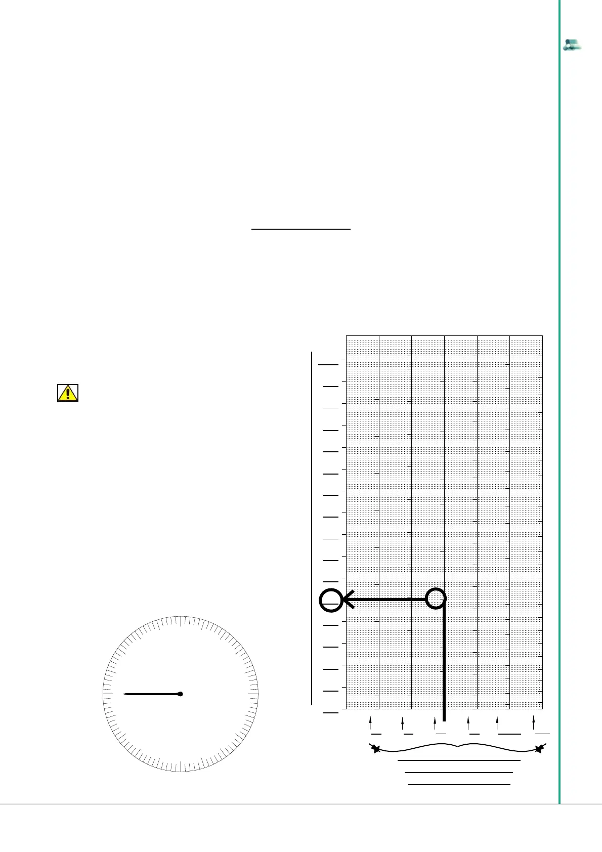
fi g ure A
Before adjusting the hand-wheel, read the value the speed controller is
set on, in the hand-wheel panel. The hand-wheel panel is shown
in fi gure A. Below, in the table placed to the side as an example, one can
obtain the value of the LDPU revolutions.
For example, if we are in presence of a size “10” speed controller and
the hand-wheel (fi gure A) has the arrow on 5, simply trace a vertical
line, starting from the column corresponding to the “10” size, until 5,
indicated by the hand-wheel, to then proceed horizontally, towards the
left until reading the corresponding number of revolutions at which the
speed controller operates, i.e. 450 RPM.
This operation, i.e. the speed variation of the speed controller, must be
carried out by the operator in charge of running the plant:
he must act on the mechanical speed controller hand-wheel, only after
having started the LDPU.
CORRESPONDING OUTPUT REVOLUTIONS [RPM] OF THE SPEED CONTROLLER
QUANTITIES REFERRED TO
MOTOVARIO/SPAGGIARI
SPEED CONTROLLERS