O.M.A.C. s.r.l.
Via Giovanni Falcone, 8 42048 Rubiera (RE) - Italy Tel.0522/629371 - 629923 Fax 0522/628980
Rev.4 del 01/2011 O.M.A.C. s.r.l.
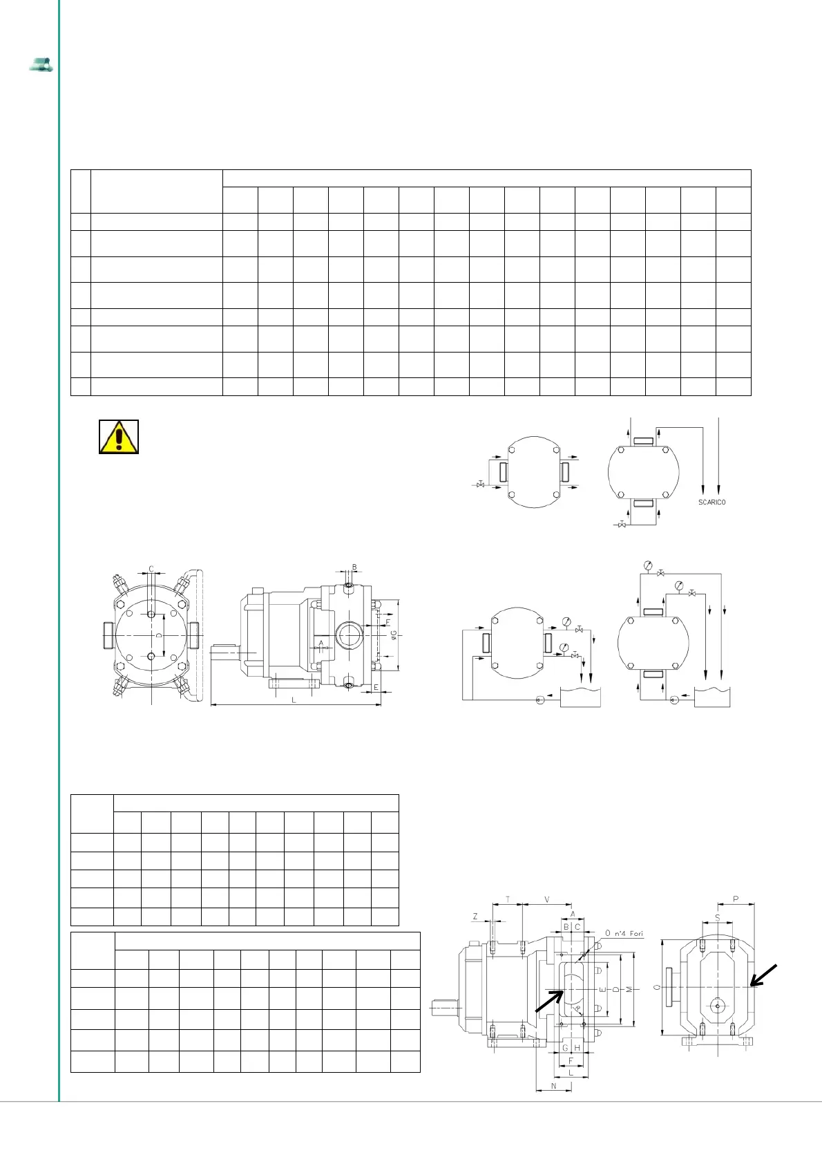
1.3.9 Dimensions of pumping case connections, equipped with heating/cooling chamber and fl ushing
seals.
At times the Customer may request, according to the production needs, to heat/cool the pumping chamber or to fi t some fl ushed mechanical seals (for
further information please refer to section 1.11). The dimensions of the heating / cooling fl uid inlet and outlet holes of the pumping chamber and the
dimensions of the fl ushing holes of the mechanical seals are shown in the following table and are divided per pump model.
Dimensions A, B and C are expressed in inches, dimensions D, E, F, G, L in millimetres.
POS.
DESCRIPTION
PUMP MODEL
B100
B105
B110
B115 B215 B220 B325 B330 B390 B430 B440 B470 B490 B550 B660 B680
A Seal fl ushing holes - 1/8” 1/8” 1/8” 1/8” 1/8” 1/8” 1/8” 1/8” 1/8” 1/8” 1/8” 1/8” 1/4” 1/4”
B
Rotor case heating fl uid
connections size
- 1/2” 1/2” 1/2” 1/2” 1/2” 1/2” 1/2” 1/2” 1/2” 3/4” 3/4” 3/4” 3/4” 3/4”
C
End cover heating fl uid
connections size
1/8” 1/2” 1/2” 1/2” 1/2” 1/2” 1/2” 1/2” 1/2” 1/2” 3/4” 3/4” 3/4” 3/4” 3/4”
D
Distance between end
cover fl uid connections
56 75 75 100 100 122 122 122 150 150 180 180 180 300 300
E Nut heigh 12 15 15 18 18 18 18 18 22 22 25 25 24 27 27
F
End cover heating
chamber thickness
17 20 20 20 20 20 20 20 18 18 23 23 23 30 30
G
End cover heating
chamber diameter
104 126 126 156 156 179 179 179 219 219 280 280 280 400 400
L Pump lenght 256 295.5 307.5 367.5 382.5 461 476 476 543.5 563.5 654 684 637 807 867
1.3.10 Suction inlet dimensions in “widened rectangular inlet port” version of the B Series lobe positive
displacement pump
To facilitate handling of viscous fl uids or fl uids that contain a percentage of solids, O.M.A.C. s.r.l. has designed and made a B series lobe displacement
pump with a widened rectangular suction inlet (see indication in the drawing below).
PUMP
MOD.
POSITION
A B C D E F G H L M
B115 40 22 18 90 70 42 23 19 61 120
B220 55 31 24 110 92 54 32 22 72 150
B330 75 37 38 146 133 65 32 33 93 176
B440 75 32.5 42.5 230 180 81 40.5 40.5 115 248
B490 107 67 40 230 180 107 69 38 143 256
PUMP
MOD.
POSITION
N O P Q R S T U V Z
B115 67 M6 64 154 6 55 35 93.5 94 M8
B220 87 M8 78 210 15 67 67 127.5 114 M10
B330 103 M8 95 236 12.5 70 85 145 143.5 M12
B440 116.5 M10 122.5 320 12.5 100 100 192.5 161.5 M14
B490 173 M12 152.5 370 12.5 130 135 230 190.5 M20
ATTENTION
The drawing on the right shows the connection method of the
seals fl ushing system, with indication of the fl ushing liquid cir-
culation direction. Carefully read and understand the fl ushing
operation methods described in section 5.7.4.
HEATING / COOLING
PUMPING CASE AND FRONT COVER
FLUSHING DISPOSABLE CIRCUIT
FLUSHING CIRCUIT WITH TANK
For design requirements, this optional feature is available only on models
B115, B220, B330, B440, B490. The fi gure below shows the position of the
widened rectangular inlet on the pumping chamber, and the table shows,
according to the model type, the dimensions of the inlet, as well as the
dimensions of the B Series lobe displacement pump.