3
O.M.A.C. s.r.l.
Via Giovanni Falcone, 8 42048 Rubiera (RE) - Italy Tel.0522/629371 - 629923 Fax 0522/628980
E-mail:info@omacpompe.com SitoWeb:www.omacpompe.com
Rev.4 del 01/2011 O.M.A.C. s.r.l.
Chap.3 - pag.
STAGE 1: PLACEMENT
Following the provisions of section 3.3.1 - Preliminary checks - and on the basis of the indications of chapter 2 of this use and maintenance manual, the
operators must see to harness and handle the LDPU to place it in the position required by the Customer and specifi ed in the plant layout.
During this stage, one will need to use a forklift with suitable capacity, driven by personnel appointed by the Customer, as per chapter 2. One must pay
utmost attention in placing the LDPU in the envisioned position without intervening on the unit piping.
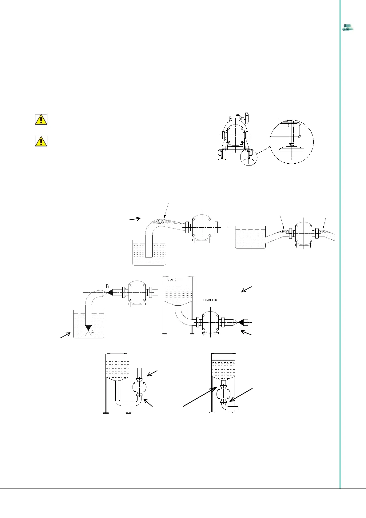
In the LDPU version with adjustable feet, the operators will see to measuring the height of the suction and delivery piping of the unit, after having positio-
ned the machine. Then they must adjust the height of the unit openings at the measured height, acting on the adjustable feet. Once the second operation
is complete, they can free the unit from the harnesses and proceed with stage 2 - fi x ing and installation, hooking the openings of the unit pumping part
by screwing them onto the plant piping.
ATTENTION
Check that there are the special non-slip rubber rings in the feet.
ATTENTION
Ensure the Customer plant is aligned properly with the suction
and delivery openings of the LDPU.
When installing the LDPU it is essential to leave a enough space for maintenance and possible removal.
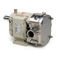
During STAGE 1 relating to the POSITIONING it is recommended to avoid the followings situations:
STAGE 2: FIXING AND INSTALLATION ON SITE
Once the LDPU has been positioned and aligned to the Customer plant, proceed to fi x and install in the plant. Since fi xing between the plant and the
LDPU involves the suction inlet and delivery outlet of the pumping body, listed below are the maximum values of forces and moments, indicated with EF
and EM, which the pump body and consequently the LDPU, of which it is a part, can sustain, as maximum values, during standard operation.
• in the event there are horizontal
tracts of suction piping, make sure these are
slightly inclined upwards to prevent air pockets
from forming which would inhibit perfect priming
of the LDPU;
WRONG!!!
AIR
AIR
WRONG!!!
AIR
• if the
LDPU is not un-
der the head, in
the suction tract
provide a foot or
check valve to
maintain priming;
• if the LDPU is connected to a
vacuum tank, one must reduce the load
leaks due to the suction piping as much
as possible;
• install a check valve on the
delivery tract to prevent the back-fl ow of
air or liquid during interruptions of servi-
ce in order to maintain the pipes com-
pletely full and to facilitate starting when
loaded.
RIGHT!!!
A = foot valve
or
B = check valve
RIGHT!!!
• when applying in ver-
tical position avoid connecting
the suction inlet to the lower side
and the delivery outlet to the
upper side. The proper confi gu-
ration consists in connecting the
suction pipe to the upper side
and the delivery pipe to the lower
side.
WRONG!!!
DISCHARGE
SUCTION
RIGHT!!!
DISCHARGE
SUCTION