The manufacturer reserves the right to make changes without prior notice!
GB
Operating instructions for
MINILIFT PUMP UNIT C40 - C50
Page: D846M5L.011
Date of Issue: 14/03/2012
Version: Rev. 02
Approved: UT
The standard control unit box includes
(see Figure 9):
• Electric motor U (1 - brown)
• Electric motor V (2 - blue)
• Grounding bolt
• Motor guard (3 - black)
• Motor guard (4 - gray)
• Oil heating resistance (option)(5-6)
• Oil thermal protection (70°)
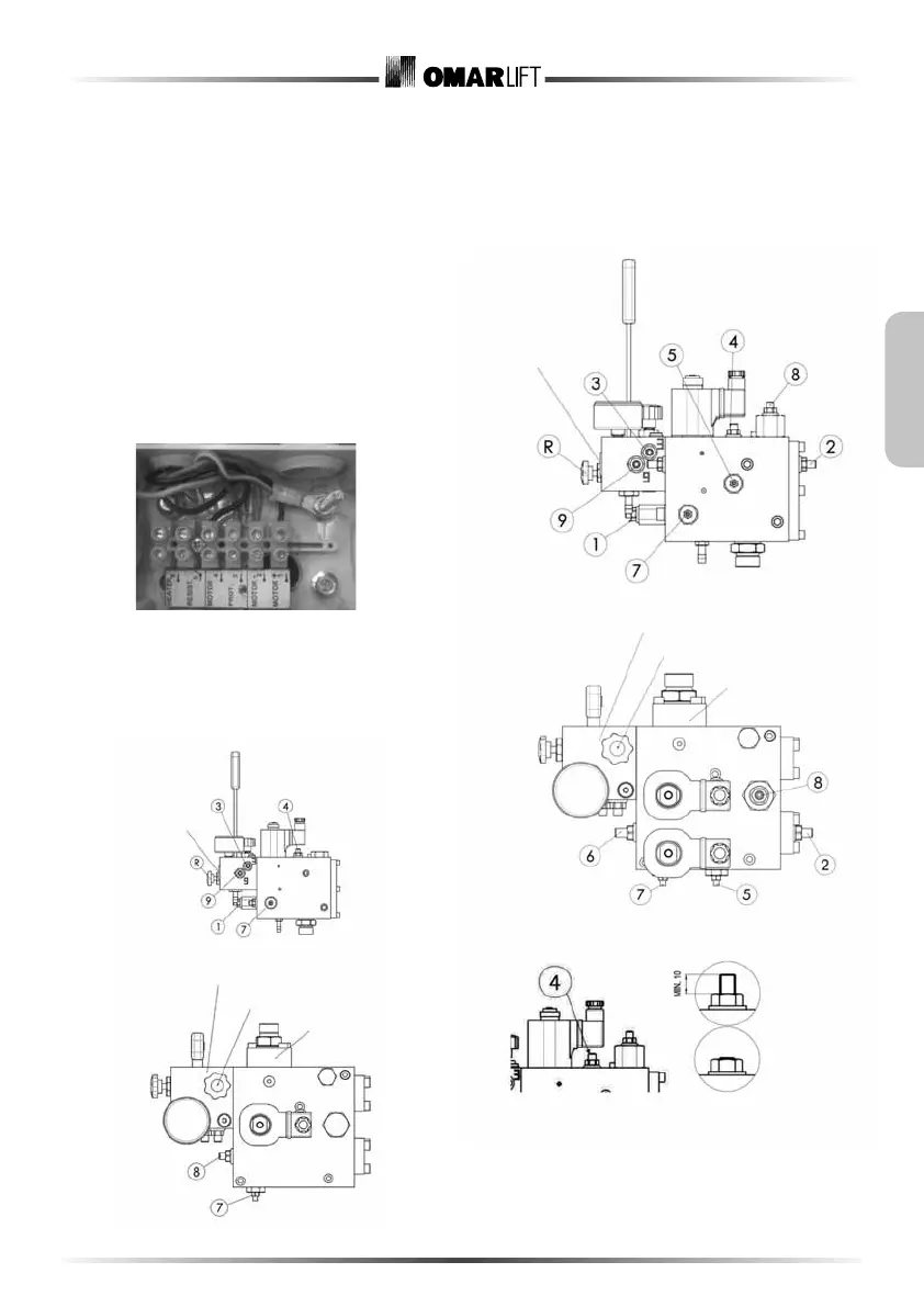
6 Calibration and adjustment of MINILIFT valve
6.1. Minilift valve, 1 speed
Figure 9
Figure 10
Figure 11
Inspection connection
pressure gauge1/2” Gas
PM Lift Directive
Emergency pushbutton
Filter block
6.2. Minilift valve, 2-speed
Figure 12
Figure 13
Figure 14
Inspection connection
pressure gauge1/2” Gas
PM Lift Directive
Emergency pushbutton
Filter block
Normal
operation
Screw tightened
completely
 Loading...