CP SB1 User Manual
22
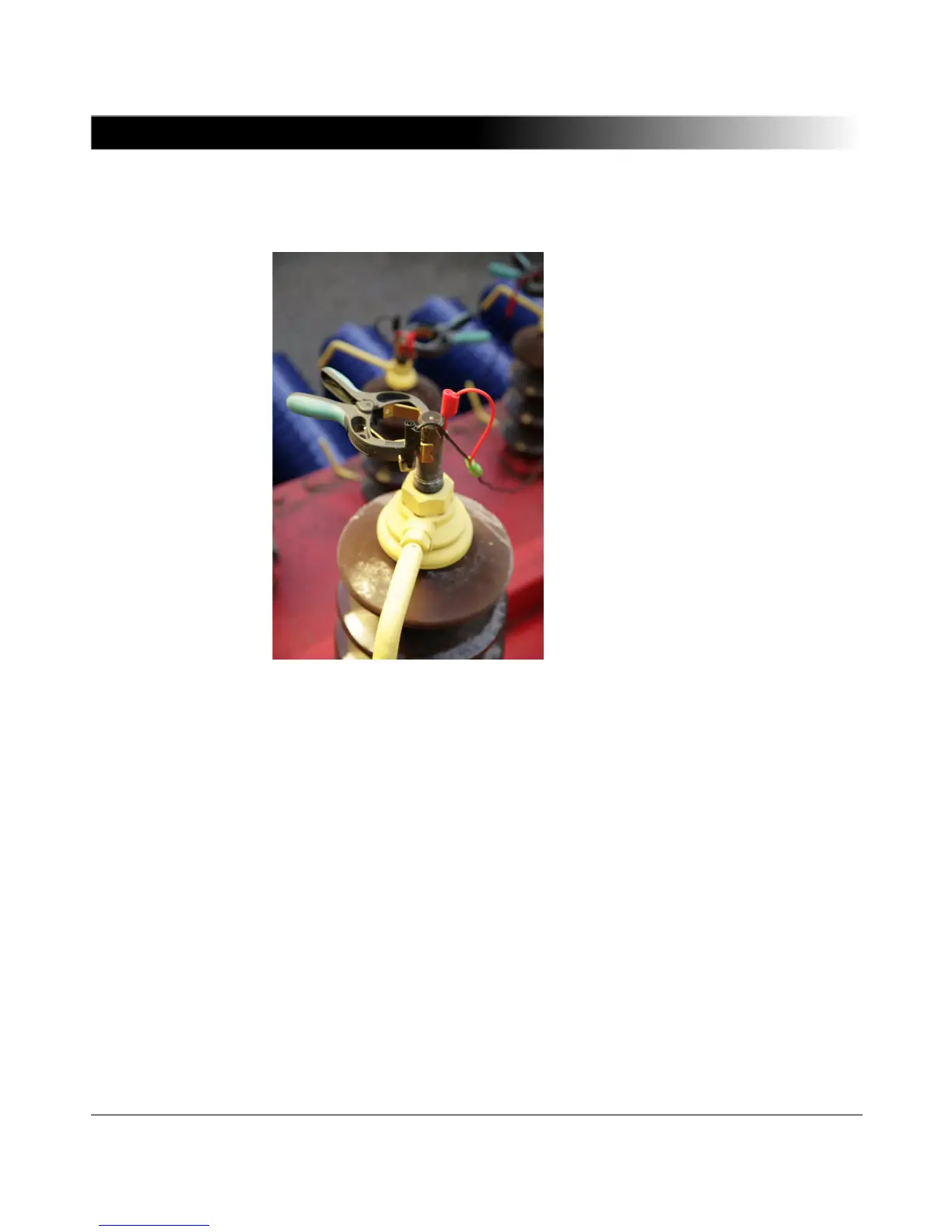
8. Connect the cables to the Kelvin clamps. Make sure that the cables show
upwards and that each colour is connected to a different phase.
9. Connect the cables from the Kelvin clamps’ voltage sense outputs to the
CP SB1’s transformer inputs. Observe the color code.
10.Make sure to measure the voltage to ground at the terminals of the tap
changer. If no voltage is measured, connect the flexible terminal adapters to
the "up" and "down" terminals of the tap changer.
11.Connect the cables ("up", "down") to the CP SB1.
12.Connect the CP SB1 to the CPC 100 according to 1.3 "Functional
Components of the CP SB1" on page 15.
13.Switch on the power supply of the tap changer.
14.Remove all grounding connections of the terminals except one per winding.
Use Neutral (N) for the grounding connection if accessible.
15.Start the measurement according to 3.4.2 "Performing Measurements with
TRRatio" on page 42 and 3.5.2 "Performing Winding Resistance
Measurements" on page 49.
 Loading...