CP SB1 User Manual
70
5.1.8 Dynamic Behavior of the Diverter Switch
To date, only the static behavior of the contact resistances has been taken into
account in maintenance testing. With a dynamic resistance measurement, the
dynamic behavior of the diverter switch can be analyzed.
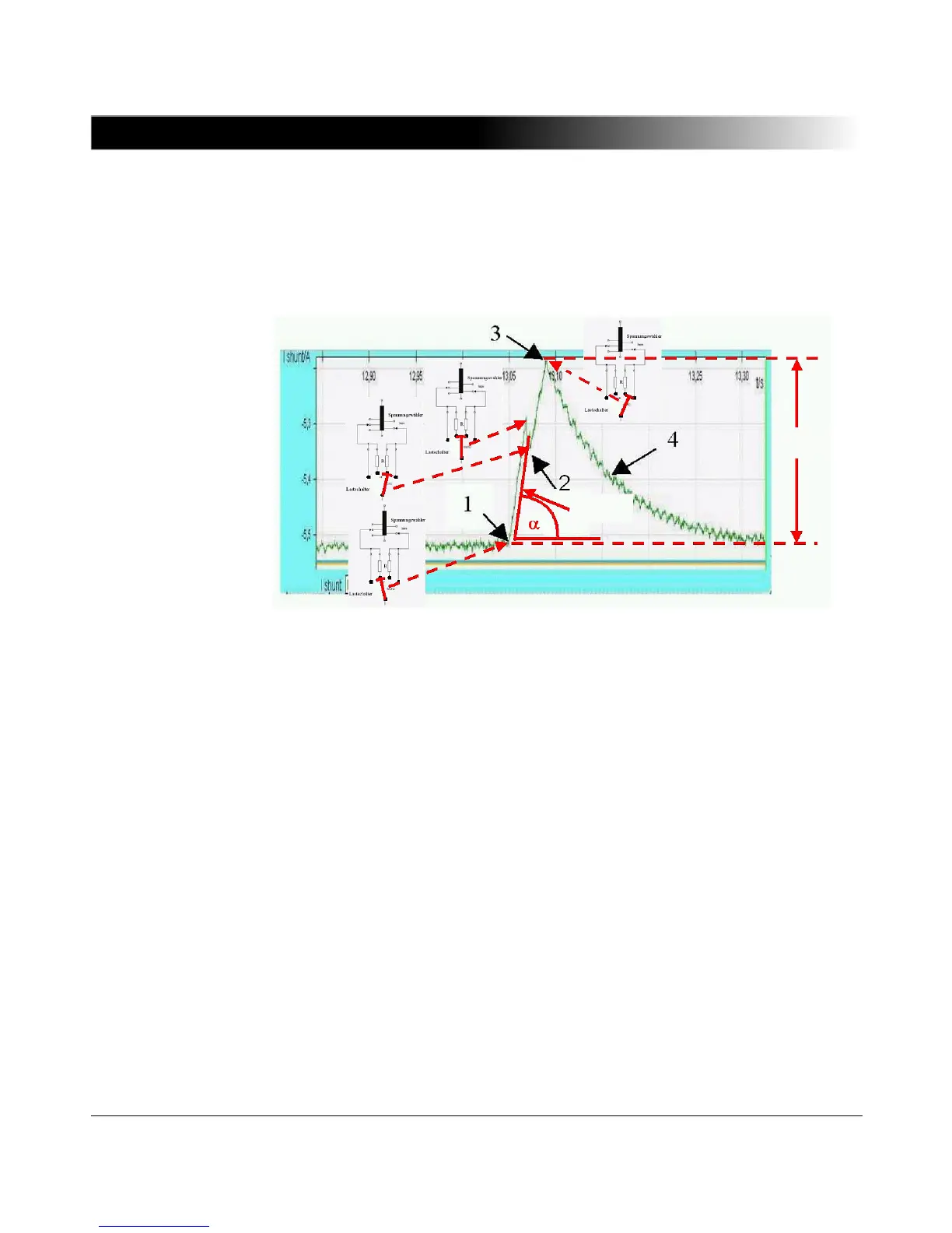
Figure 5-13 Dynamic resistance measurement for analysis of the diverter
switch
1 = Diverter switch commutes from the first tap to the first commutation resistor
2 = The second commutation resistor is switched in parallel
3 = Commutation to the second tap (direct contact)
4 = Charging the additional windings
For the dynamic resistance measurement, the test current should be as low as
possible. Otherwise, short interruptions or bouncing of the diverter switch
contacts cannot be detected. In this case, the initiated arc has the effect of
shortening the open contacts internally. Comparison to "fingerprint" results,
which were taken when the item was in a known (good) condition, allows for an
efficient analysis.
A glitch detector measures the peak of the ripple and the slope of the measuring
current, as these are important criteria for correct switching (without bouncing or
other short interruptions). If the switching process is interrupted, even if only for
a short-time, the ripple (= I
max
- I
min
) and the slope of the current change (di/dt)
increase. The values for all taps and particularly the values for the three phases
are compared. Major deviations from the mean values indicate faulty switching.
For a more detailed analysis, a transient recorder can be used to record the
 Loading...